

Next: 2D Numerical Example
Up: Subsalt reservoir monitoring: Ayeni
Previous: Introduction
The large velocity contrast at salt boundaries, complexity of seismic travel paths, lack of amplitude reciprocity, and
effects from peaks and pits Muerdter and Ratcliff (2001) are some of the causes of illumination problems in sub-salt reservoirs.
Several acquisition techniques (wide-, rich-, and full-azimuth surveys, ocean-bottom surveys and VSPs) now help improve
illumination of subsalt reservoirs Sava (2006). Also, 3D prestack
depth migration (PSDM) has been shown to be an important processing
tool for sub-salt imaging Biondi et al. (1999); Malaguti et al. (2001); Ratcliff et al. (1994).
Although many advanced acquisition and processing techniques help to correctly image reflectors beneath most complex/detached
and/or steeply dipping salt bodies, the seismic amplitudes recovered from most of these techniques are not
usually reliable. Rickett (2003) suggested weighting functions derived from reference images to correct for amplitude
distortions caused by illumination problems. While amplitudes recovered from such normalization schemes meet many imaging requirements, their
reliability may be considerably lower in scenarios such as sub-salt reservoir monitoring where slight inaccuracies could be
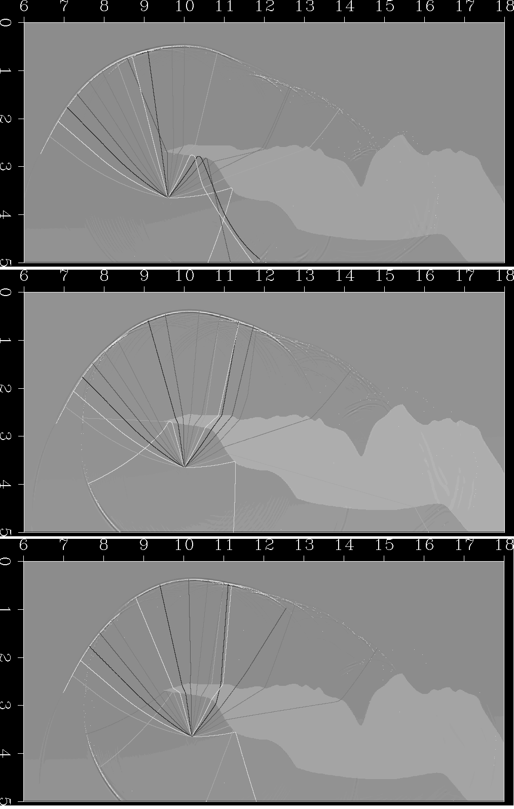
very important. As shown in Figure ![[*]](http://sepwww.stanford.edu/latex2html/cross_ref_motif.gif) , slight changes in shot/image position (and/or acquisition geometry) could
result in widely different (and complex) travel paths of sub-salt reflections. Also, artifacts from the migration process tend to
obscure the weak signals from these reflectors Clapp (2005) and even small differences between these artifacts may considerably contaminate
the time-lapse response. In many cases, there is no guarantee that the cross-equalization process would leave the desired time-lapse effect intact.
These factors, coupled with the original illumination problem, make subsalt reservoir monitoring a difficult task.
, slight changes in shot/image position (and/or acquisition geometry) could
result in widely different (and complex) travel paths of sub-salt reflections. Also, artifacts from the migration process tend to
obscure the weak signals from these reflectors Clapp (2005) and even small differences between these artifacts may considerably contaminate
the time-lapse response. In many cases, there is no guarantee that the cross-equalization process would leave the desired time-lapse effect intact.
These factors, coupled with the original illumination problem, make subsalt reservoir monitoring a difficult task.
Biond_Ray
Figure 1 Subsalt Illumination effects: wave-field/ray-tracing modeling.
Notice the dramatic changes in raypaths as the image point shifts from left (top) to right (bottom).


Next: 2D Numerical Example
Up: Subsalt reservoir monitoring: Ayeni
Previous: Introduction
Stanford Exploration Project
5/6/2007
![[*]](http://sepwww.stanford.edu/latex2html/cross_ref_motif.gif) , slight changes in shot/image position (and/or acquisition geometry) could
result in widely different (and complex) travel paths of sub-salt reflections. Also, artifacts from the migration process tend to
obscure the weak signals from these reflectors Clapp (2005) and even small differences between these artifacts may considerably contaminate
the time-lapse response. In many cases, there is no guarantee that the cross-equalization process would leave the desired time-lapse effect intact.
These factors, coupled with the original illumination problem, make subsalt reservoir monitoring a difficult task.
, slight changes in shot/image position (and/or acquisition geometry) could
result in widely different (and complex) travel paths of sub-salt reflections. Also, artifacts from the migration process tend to
obscure the weak signals from these reflectors Clapp (2005) and even small differences between these artifacts may considerably contaminate
the time-lapse response. In many cases, there is no guarantee that the cross-equalization process would leave the desired time-lapse effect intact.
These factors, coupled with the original illumination problem, make subsalt reservoir monitoring a difficult task.
