


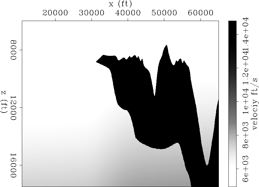
The Sigsbee data set was modeled by simulating the geological setting found on the Sigsbee escarpment in the deep-water Gulf of Mexico. The model exhibits the illumination problems due to the complex salt shape, characterized by a rugose salt top (see Figure ![[*]](http://sepwww.stanford.edu/latex2html/cross_ref_motif.gif) ). We choose a target zone ( see Figure ) to see the effects of illumination on imaging close to the salt.
). We choose a target zone ( see Figure ) to see the effects of illumination on imaging close to the salt.
 |


 |
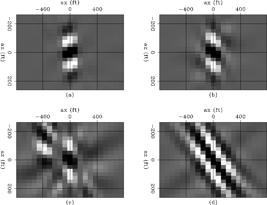 |
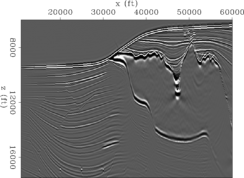
Figure shows the shot-profile migration image (using cross-correlation imaging condition) corresponding to the portion of Sigsbee model shown in figure . Notice how the amplitudes of the reflectors fade away as they get closer to the salt.
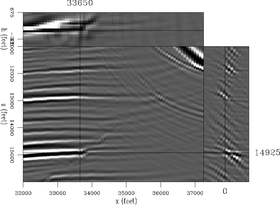
Figure shows a ![]() coefficient filter (target-oriented Hessian) at constant depth as the x coordinate moves from the sediments to the salt boundary. Figure a shows point 1, with coordinates
coefficient filter (target-oriented Hessian) at constant depth as the x coordinate moves from the sediments to the salt boundary. Figure a shows point 1, with coordinates ![]() (far from the salt). Figure b shows point 2, with coordinates
(far from the salt). Figure b shows point 2, with coordinates ![]() . Figure c shows point 3, with coordinates
. Figure c shows point 3, with coordinates ![]() . Figure d shows point 4, with coordinates
. Figure d shows point 4, with coordinates ![]() .
.
The shape of the filter is not dependent only on the acquisition geometry but the subsurface geometry (presence of the salt body). In the area unaffected by the salt the filter looks the same as is the constant velocity case, but as we get closer to the salt the illumination varies (in intensity and angle) and the filter behaves differently. This is due to a focusing and defocusing effect created by the salt. To correct this effect we computed the least-squares inverse image.
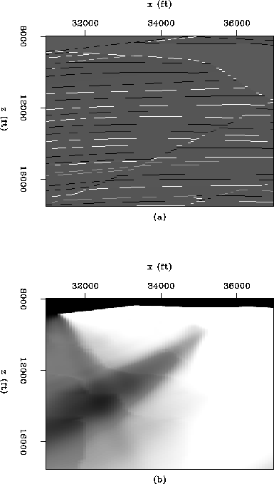
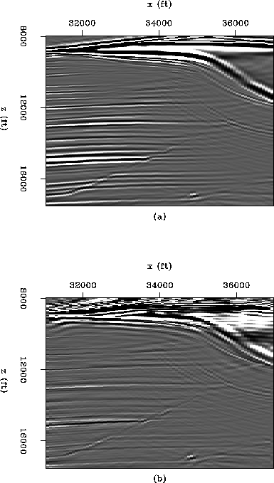
Figure shows a comparison between the
migration and the postack inversion images in the target area. The
reflection coefficients are shown in Figure
a. Notice the position of the faults. Figure
b shows the illumination, which is the
diagonal of the Hessian matrix. Notice the decrease in the
illumination as it gets closer to the salt with the exception of a
narrow strip where energy focuses close to the salt. The migration
result is shown in Figure a. The reflectors
dim out as they get closer to the salt. In contrast, Figure
b shows the postack inversion result, the
resolution increases and the section looks more balanced. The fault
can be followeded and interpreted closer to the salt body.
 |
 |
The salt, in the inversion image looks distorted. This is due to the
fact that data values (migration) in the salt boundary are bigger than
everywhere else (Figure a), and so are the
data residuals. Thus, the solver expends most of the time decreasing
the residuals in that area. A residual weight designed to decrease the
salt contribution should improve the image. Figures
and compare the migration
and the prestack inversion images in the reduced
target area. The resolution increases, and the section looks more
balanced in the prestack inversion result. The fault can be follow
and interpreted closer to the salt body in the inversion image.
 |
 |