


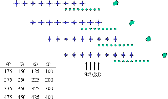
![[*]](http://sepwww.stanford.edu/latex2html/cross_ref_motif.gif) which
shows the offset distribution inline for a few adjacent CMPs. Only every
fourth CMP the offset distribution repeats. Although not shown, the situation
in the crossline direction is worse. There are
20 different crossline offsets (from -475 to 475 m), but for any CMP line taken
at a fixed crossline position, all traces correspond to the same crossline offset.
which
shows the offset distribution inline for a few adjacent CMPs. Only every
fourth CMP the offset distribution repeats. Although not shown, the situation
in the crossline direction is worse. There are
20 different crossline offsets (from -475 to 475 m), but for any CMP line taken
at a fixed crossline position, all traces correspond to the same crossline offset.
The input to the source-receiver migration algorithm is a regular 5-D cube
![]()
 |

In order to make a more manageable dataset, further data reduction is
necessary. Here we are particularly interested in the effect of crossline
dip in the moveout of the multiples after migration, therefore we chose
to subsample the data in the inline coordinates only. We subsampled the
inline CMP axis such that every other CMP was discarded. This has the advantage
of not only halving the number of CMPs but also halving the number of inline
offsets as can be seen in Figure since now the inline
offset interval is 50 m rather than 25 m. We also subsampled the time
axis to 16 ms, which required that the
data be filtered to a maximum frequency of 32 Hz even though the original
wavelet had frequencies up to about 60 Hz as shown in
Figure . This is appropriate in this case because vertical
resolution is not critical for our purposes. Finally, we limited the inline
offsets to 4000 m which sacrifices the steeper flanks of the moveout of the
multiples as shown in Figure . With these reductions, the
dataset size becomes about 70 GB after some padding in all spatial directions
to avoid or at least lessen migration artifacts.
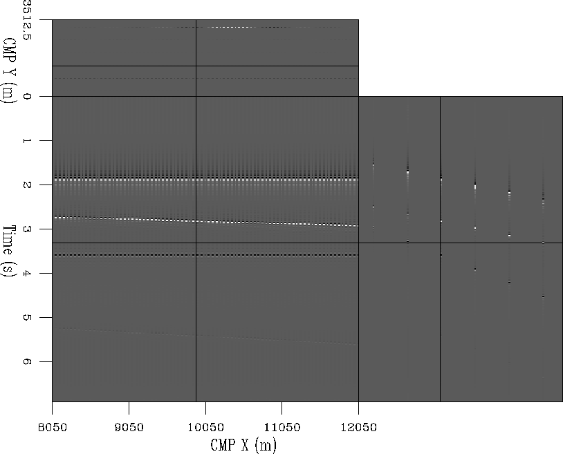
Figure shows a near offset cube of the five-dimensional
selected dataset. Notice
that there are only six crossline CMPs for a given inline CMP location,
corresponding to the six sail lines, and there is no data redundancy in the
crossline direction. Similarly, only every other inline CMP position has a
trace with a given crossline CMP location because of the dual shot geometry.
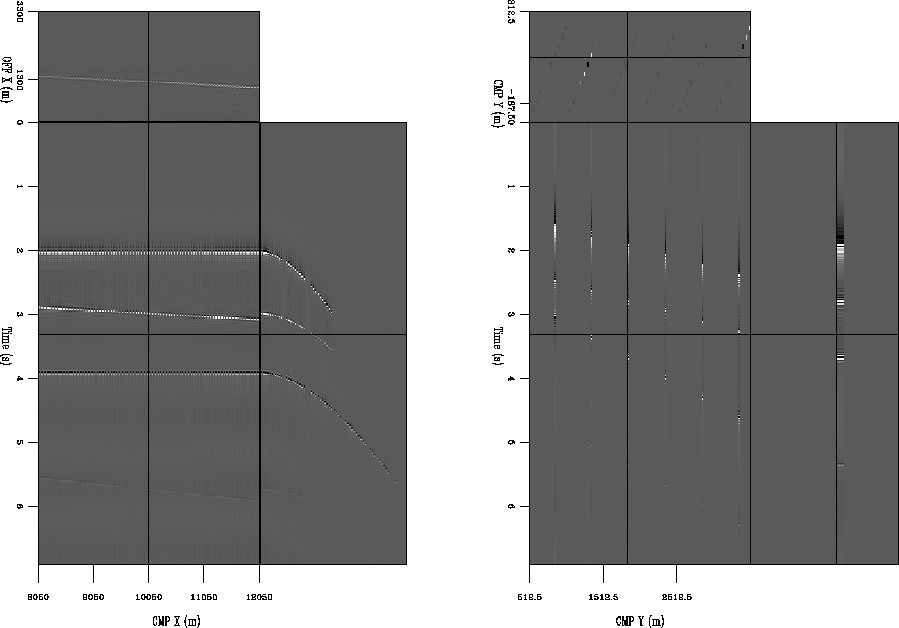
Panel (a) of Figure shows the inline and distribution
of offsets for
an inline CMP section taken at crossline CMP position 2212.5 and crossline
offset of -12.5 m. Here again we note the on-off pattern of the offset
distribution due to the dual shot source as indicated in the sketch in
Figure . Similarly, panel (b) of Figure
shows the distribution of crossline offsets
for a CMP section in the crossline direction taken at inline CMP location
8400 and inline offset of 100 m.
 |


 |