 |
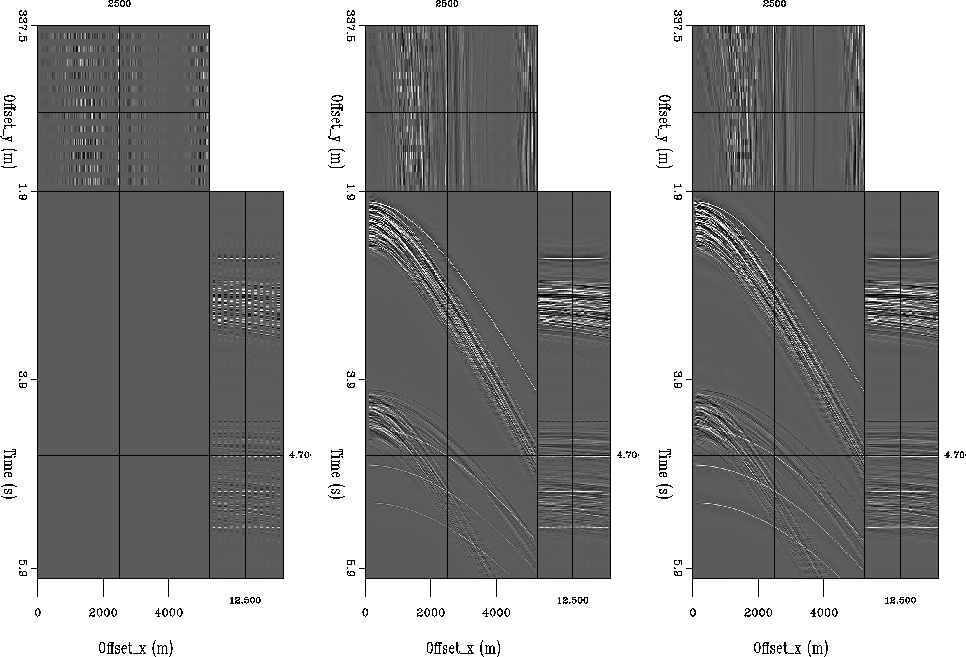
Figure 4 Receiver cable interpolation, factor of 2. From left to right: original input shot gather; result of 2D interpolation; result of 3D interpolation.
![[*]](http://sepwww.stanford.edu/latex2html/movie.gif)
 |
![[*]](http://sepwww.stanford.edu/latex2html/movie.gif)
As we can see in Figure ![[*]](http://sepwww.stanford.edu/latex2html/cross_ref_motif.gif) , here interpolating in 2D is
noticeably worse than in 3D. In particular, the water-bottom multiple, the
diffractions at near offset, and the diffracted multiples at far offset were
not correctly interpolated with the 2D filter, and were correctly
interpolated in 3D. This is because the 2D interpolation acted over
receiver-cable and time, so no trends along the receiver cable axis were captured.
The added in-line receiver axis in the 3D PEF
interpolation allowed much more information to be gathered from the data.
, here interpolating in 2D is
noticeably worse than in 3D. In particular, the water-bottom multiple, the
diffractions at near offset, and the diffracted multiples at far offset were
not correctly interpolated with the 2D filter, and were correctly
interpolated in 3D. This is because the 2D interpolation acted over
receiver-cable and time, so no trends along the receiver cable axis were captured.
The added in-line receiver axis in the 3D PEF
interpolation allowed much more information to be gathered from the data.
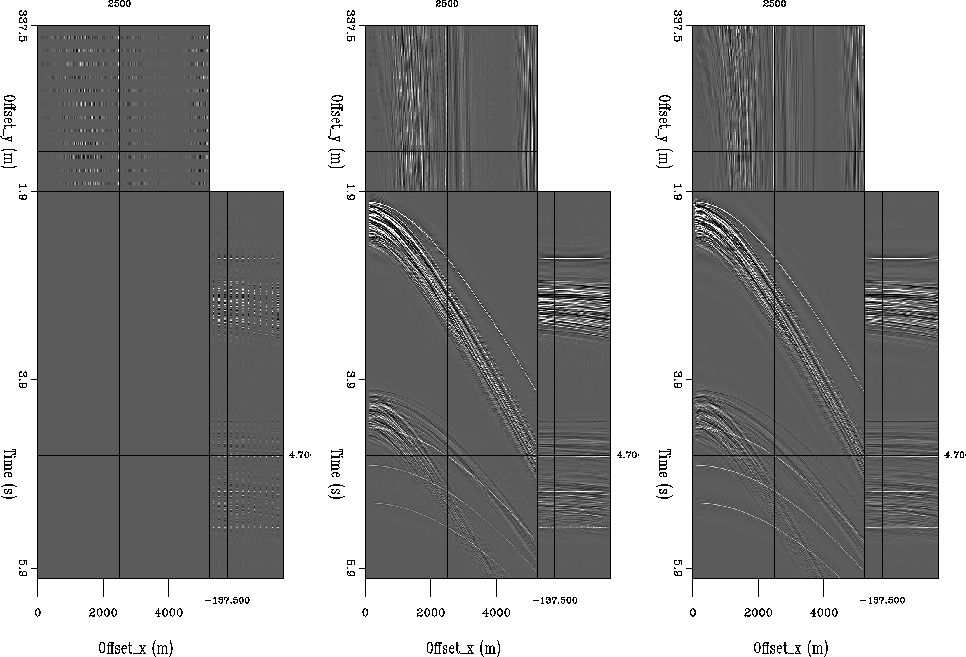
Once the number of receiver cables has been doubled by interpolation, it can be
doubled again to get to the desired factor of 4. This is shown in Figure
![[*]](http://sepwww.stanford.edu/latex2html/cross_ref_motif.gif) . The interpolation differences are even more pronounced between
the 2D and 3D interpolations. The end result of the cross-line interpolation in
3D is quite promising, and the poor performance of the 2D result shows that
extra dimensionality is a much more important factor when the axis of interpolation
is poorly sampled.
. The interpolation differences are even more pronounced between
the 2D and 3D interpolations. The end result of the cross-line interpolation in
3D is quite promising, and the poor performance of the 2D result shows that
extra dimensionality is a much more important factor when the axis of interpolation
is poorly sampled.
 |
![[*]](http://sepwww.stanford.edu/latex2html/movie.gif)
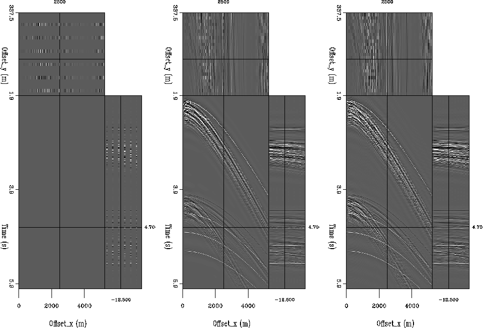
Twelve receiver cables is not typical for a marine acquisition. Many 3D surveys
use a smaller number of cables, which can be as low as 4 in a speculative survey.
Figure ![[*]](http://sepwww.stanford.edu/latex2html/cross_ref_motif.gif) shows the results of interpolating from 6
receiver cables up to 24. While the result is not poor, it is not nearly as
good as with the original 12 cables. This is most noticeable at the near offsets.
shows the results of interpolating from 6
receiver cables up to 24. While the result is not poor, it is not nearly as
good as with the original 12 cables. This is most noticeable at the near offsets.
 |
![[*]](http://sepwww.stanford.edu/latex2html/movie.gif)