


![[*]](http://sepwww.stanford.edu/latex2html/cross_ref_motif.gif) ). We chose an example event from this dataset because of its dense, approximately regular sampling and because the scattered wavefield contains clearly discernible arrivals with time variable dips. We feel that although this dataset makes an excellent example it is not an isolated case and this method would be effective with other densely sampled datasets.
). We chose an example event from this dataset because of its dense, approximately regular sampling and because the scattered wavefield contains clearly discernible arrivals with time variable dips. We feel that although this dataset makes an excellent example it is not an isolated case and this method would be effective with other densely sampled datasets.
Figure shows a high resolution radon panel of the P component (Figure a) followed by the recorded data (Figure b) , the estimated signal (Figure c), and the estimate noise panel (Figure d). The radon panel (Figure a) shows the clearly focussed direct P arrival beginning centered around 0 s/km, near 30 seconds. It is followed by lower amplitude coda waves until near 120 seconds. At 120 seconds, there is a clear change in primary slowness to a peak centered at ![]() 0.04 s/km. We interpret this arrival as pP because of its timiCASC-Png and its similar slowness and character to that of the direct arrival. After application of the radon mute (white panel in Figure c), the arrival was successfully removed and the underlying coda of the direct P arrival is recovered (Figure c). The estimated noise wavefield contains the majority of the energy from the later arrival as well as some low amplitude arrivals with negative dips recorded just after the direct arrival. By examining similarities between the signal and noise wavefields we can estimate cross-contamination of arrival dips in each wavefield and evaluate the quality of our taper parameters. In this case (Figure ), the estimated signal and noise show little similarity and are comprised by a set of arrivals with distinctly different dips. This supposition is demonstrated by the clear separation of arrivals in the radon domain.
0.04 s/km. We interpret this arrival as pP because of its timiCASC-Png and its similar slowness and character to that of the direct arrival. After application of the radon mute (white panel in Figure c), the arrival was successfully removed and the underlying coda of the direct P arrival is recovered (Figure c). The estimated noise wavefield contains the majority of the energy from the later arrival as well as some low amplitude arrivals with negative dips recorded just after the direct arrival. By examining similarities between the signal and noise wavefields we can estimate cross-contamination of arrival dips in each wavefield and evaluate the quality of our taper parameters. In this case (Figure ), the estimated signal and noise show little similarity and are comprised by a set of arrivals with distinctly different dips. This supposition is demonstrated by the clear separation of arrivals in the radon domain.
Figure shows the same panels as in Figure but for the Sv component from the same event. In this case, the small relative amplitude difference between diffracted noise and specularly scattered arrivals directly following the direct P arrival makes foccusing energy in the radon domain difficult. Despite the limited focussing in the radon domain, application of the radon mute clearly separates arrivals with differing dips which are intermingled near 70 seconds (see panel b). These arrivals are visible as low amplitude radon peaks at 0.08 s/km near 45 seconds and 0.2 s/km at 70 seconds (a). These represent the forward scattered and free-surface reflected arrivals from the dipping subducting slab below. By muting dips greater than 0.2 s/km we can remove this free-surface reflection as demonstrated in the estimated noise panel in Figure c. The absence of coherent features in the estimated noise panel (Figure d) other than the energy beginning between 60 and 90 seconds indicates that we the mute successfully separates the forward and back-scattered wavefields. This example also demonstrated the potential of using the radon transform as a wavefield separation technique regardless of the relative amplitude between the wavefields identified as signal and noise.
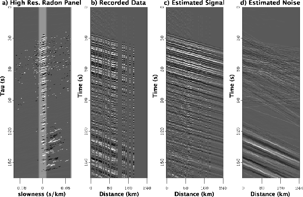 |
d) for an event recorded by the Cascadia seismic array. This radon panel (a) shows how time variable dips can be used to separate wavefields that are coincident in time. The resulting interpolated panel (c) does not contain dips significantly different from that of the direct arrival (seen in panel (d)).

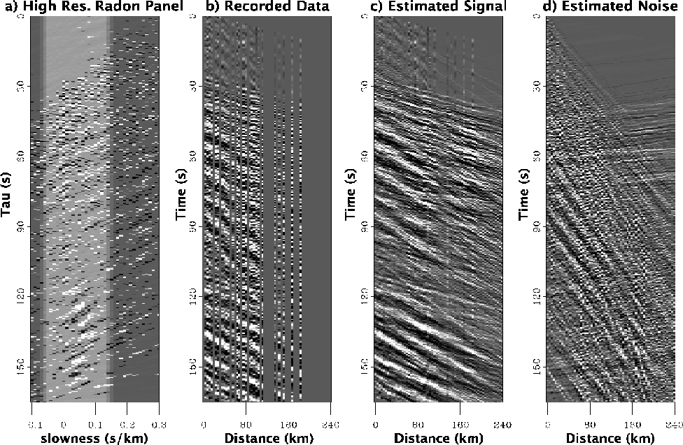 |
d) for an event recorded by the Cascadia seismic array. The radon panel appears to be poorly focussed until later