Next: Discussion
Up: Chen et al.: Reflection
Previous: Depth Controlled Reflection tomography
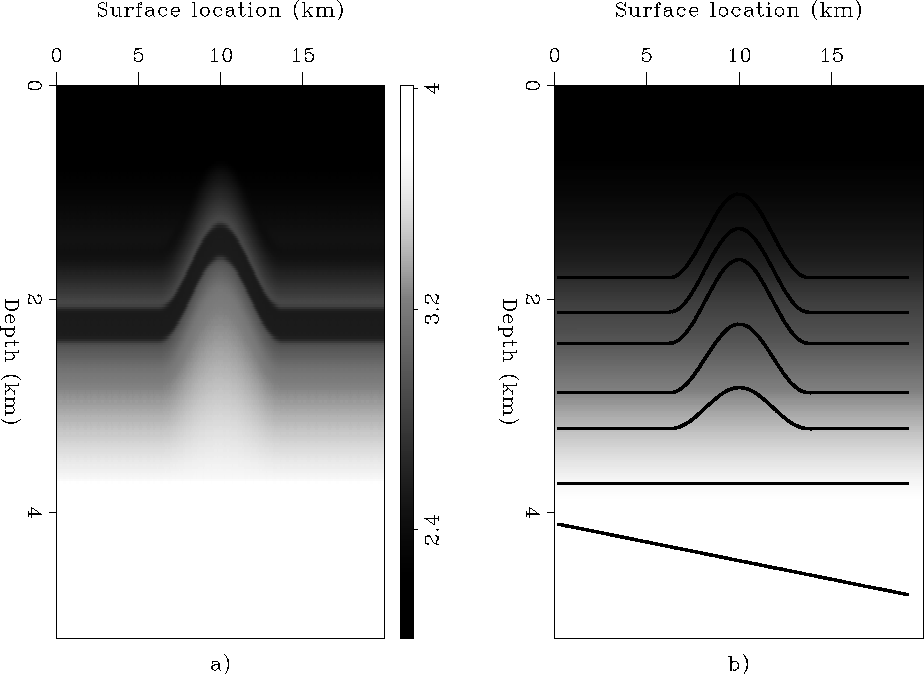
We apply our DCRT scheme to a synthetic anticline model. Figure ![[*]](http://sepwww.stanford.edu/latex2html/cross_ref_motif.gif) a and b show the correct velocity model and initial velocity model, respectively. There are seven reflectors for this synthetic model, which are overlayed on Figure b. A well is assumed at surface location x=10km.
vel
a and b show the correct velocity model and initial velocity model, respectively. There are seven reflectors for this synthetic model, which are overlayed on Figure b. A well is assumed at surface location x=10km.
vel
Figure 3 Synthetic anticline velocity model, a), and initial velocity model, b)


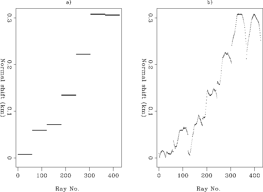
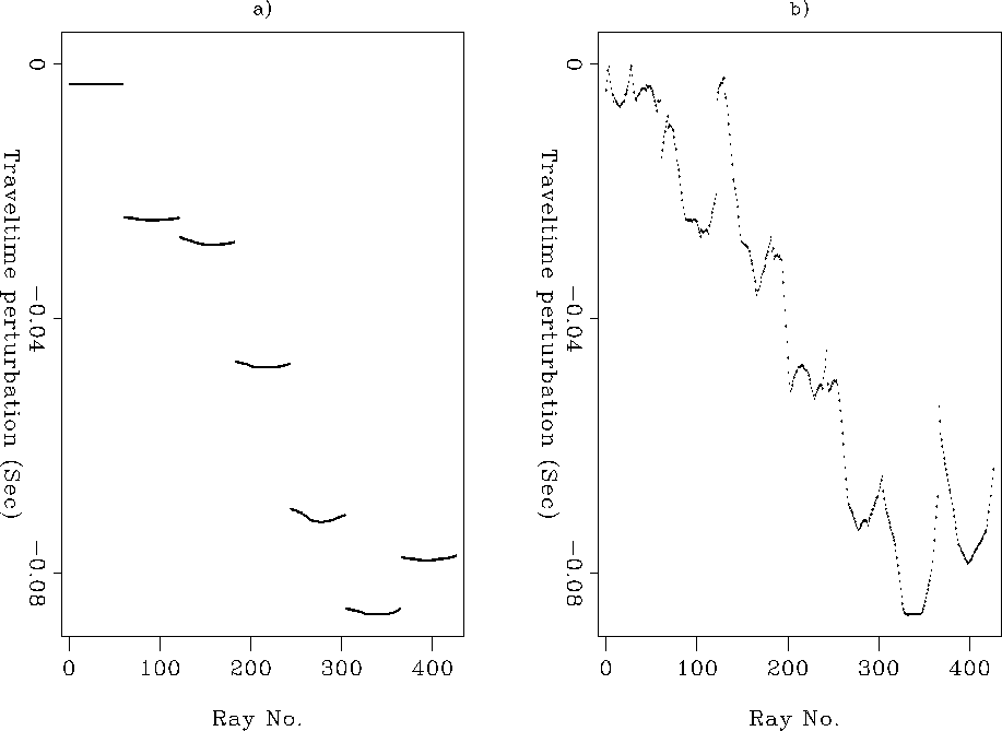
Figure shows the migration result using initial velocity model. The overlayed points are those reflection points we choose for backpropagation. For each reflector, we can only obtain the exact position for the reflection points where the well and the reflector cross. We make the assumption that all the reflection points within a local area around those reflection points have same normal shift. In Figure a, we show the assumed normal shift for all the reflection points we choose for adding depth control, which was used for DCRT in this application. As a comparison, in Figure b, we show the exact normal shift for those reflection points. After multiplying local slowness, we can obtain the corresponding traveltime perturbation along the normal ray. Figure a and b shows the assumed and exact normal ray traveltime perturbation, respectively.
crp
Figure 4 The migration result using initial velocity model. Overlayed are the reflection points chosen for adding depth points to reflection tomography
|
|  |
shift
Figure 5 a) The approximated normal shift and b) the exact normal shift, for all the reflection points chosen for adding depth control.
travtime
Figure 6 a) The approximated normal ray traveltime perturbation and b) the exact normal ray traveltime perturbation, for all the reflection points chosen for adding depth control
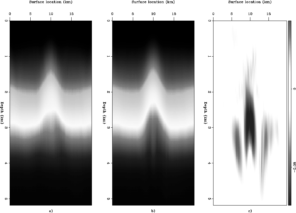
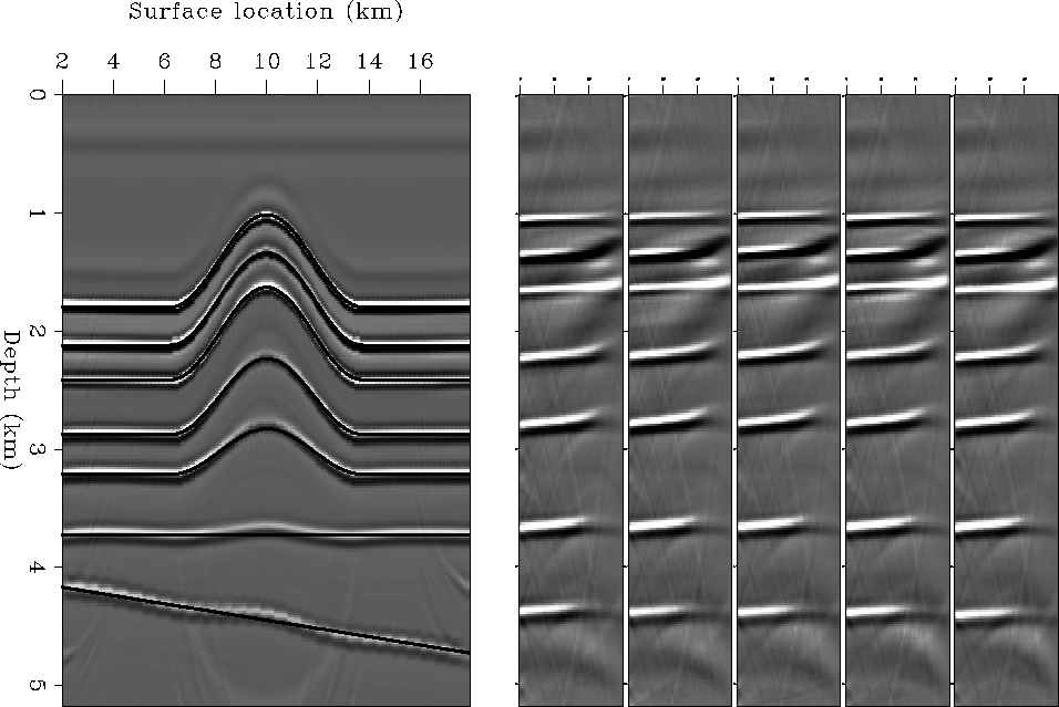
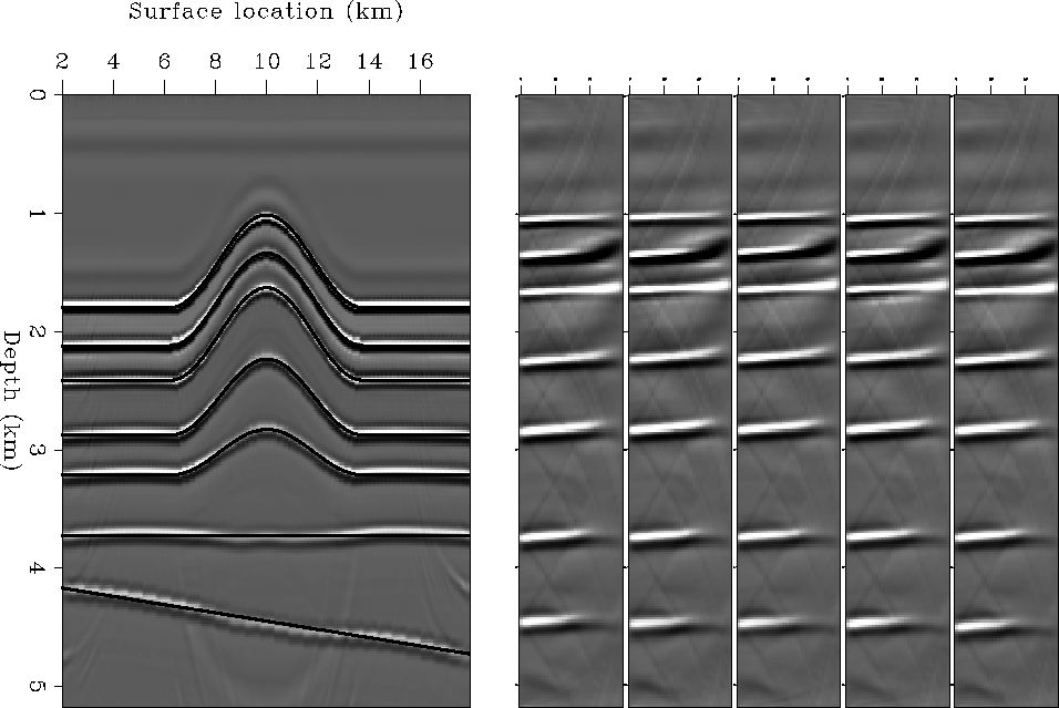
The three panels in Figure , from left to right, show the inversion result of reflection tomography, DCRT, and their difference. Notice the obvious difference around the borehole between DCRT result and regular reflection tomography result. Figure and Figure shows the migration and angle-domain common-image-gathers (ADCIGs) using velocity obtained by regular reflection tomography and DCRT, respectively. The surface positions for 5 ADCIGs, from left to right, are 9.6, 9.8, 10, 10.2, 10.4 km, respectively. Notice the improvement of the image and the reduced residual moveout around the borehole after using the DCRT method.
allvel
Figure 7 a) Reflection tomography result, b) DCRT result, and c) the difference between a) and b)
int.ref
Figure 8 a) Migration result and b) ADCGIs, using velocity from reflection tomography. The surface location for 5 ADCIGs, from left to right, are 9.6, 9.8, 10, 10.2, 10.4 km, respectively.
int.depth
Figure 9 a) Migration result and b) ADCGIs, using velocity from DCRT. The surface location for 5 ADCIGs, from left to right, are 9.6, 9.8, 10, 10.2, 10.4 km, respectively.
Next: Discussion
Up: Chen et al.: Reflection
Previous: Depth Controlled Reflection tomography
Stanford Exploration Project
10/14/2003