|
|
|
|
Imaging with multiples using linearized full-wave inversion |
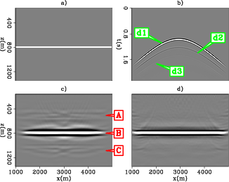
We construct a one-layered model (Figure 5 a) with ocean-bottom geometry. The only sharp interface in the migration velocity is the seabed. Figure 5 b shows the synthetic data. The labels  ,
,  and
and  correspond to the first, second, and third order events as shown in figure 2 b and c. Note that we used equation 2 to generate the synthetic data. Hence, internal multiples are absent.
Figure 5 c shows the migration image
correspond to the first, second, and third order events as shown in figure 2 b and c. Note that we used equation 2 to generate the synthetic data. Hence, internal multiples are absent.
Figure 5 c shows the migration image  . The migration image is made up of signal
  and crosstalk artifacts
  . In the figure, the label
  indicates spurious reflectors generated by migrating the primary signal (
) as if it were a multiple.
indicates spurious reflectors generated by migrating the primary signal (
) as if it were a multiple.  is the correct reflector in the image.
  is an artifact generated by migrating the multiple signal (
or
) as if it were a primary reflection. In equation form, they are denoted as follows:
is an artifact generated by migrating the multiple signal (
or
) as if it were a primary reflection. In equation form, they are denoted as follows:
 |
 |
![$\displaystyle m_{signal} + \left[m_{xtalk}\right] = m_B + \left[m_A+m_C\right]$](img32.png) |
(5) |
 |
|
 |
|
 |
|
 |
|
 |
|
 |
 ,
,  ,and
,and  correspond to the parts of the image labeled with
,
, and
in Figure 5 c.
correspond to the parts of the image labeled with
,
, and
in Figure 5 c.
 ,
,
 , and
, and
 are migration operators that correspond to different orders of reflection events. Figure 5 d shows the inversion result. Notice that the artifacts are removed from the image. In conventional imaging, if there were residual multiple energy in the data, then artifacts of type
would show up in the image. Treating those as real signal would negatively affect the interpretation of the sub-surface.
are migration operators that correspond to different orders of reflection events. Figure 5 d shows the inversion result. Notice that the artifacts are removed from the image. In conventional imaging, if there were residual multiple energy in the data, then artifacts of type
would show up in the image. Treating those as real signal would negatively affect the interpretation of the sub-surface.
|
|---|
|
Onelayerv2
Figure 5. (a) Original one layered model, (b) synthetic data, (c) migration image and (d) inversion image. |
|
|
|
|
|
|
Imaging with multiples using linearized full-wave inversion |