

Next: Slant stack and Fourier
Up: SLANT STACK
Previous: Interval velocities from slant
The determination of earth velocity from head waves
is an old subject in seismology.
Velocity measurement from head waves,
where it is possible,
refers to a specific depth--the depth of the interface--so
it has even better depth-resolving power
than an interval velocity
(the velocity of a depth interval between two reflections).
Traditionally, head-wave velocity analysis
involved identification (picking) of travel times.
Travel times are hard to pick out on noisy data.
Clayton and McMechan [1981] introduced a new method
based on the wavefield itself,
instead of on picked travel times.
They did for the velocity analysis of head waves
what wave-equation migration did for reflections.
sshead
Figure 9
The upper figure (a) contains a synthetic head-wave profile
(plotted with linear moveout).
The data is transformed by slant stack
to the lower half of the figure (b).
The result of downward continuation of this slant-stacked wavefield (b)
is shown in Figure 10.
(Clayton & McMechan)

The same idea for getting velocity from
back-scattered head waves on sections
can be used on ordinary head waves on common-midpoint gathers.
On gathers you have the extra information not on a section that
downward continuation focuses energy on zero offset.
The focus is not a featureless point.
Take original data to consist of a head wave only, with no reflection.
Downward continuation yields a focus at zero offset.
The focus is a concentrated patch of energy
oriented with the same stepout dt/dh as the original unfocused head wave.
Summing through the focus at all possible orientations (slant stack)
transforms the data  to dip space, say
  .The velocity of the earth at travel-time depth
  is found
where the seismic energy has concentrated on the
  -plane.
The velocity is given directly by
  .Given
  , v(z) is readily found.
Or the entire calculation could
be done in depth z directly instead of in travel-time depth
  .
.
Clayton and McMechan actually do the downward continuation
and the slant stack in the opposite order.
They slant stack first and then downward continue.
In principle these processes
can be done in either order.
Remember that we are bootstrapping to the correct earth velocity.
Slant stacking does not depend on the earth's velocity,
but downward continuation does.
Slant stacking need be done only once if it is done first,
which is why Clayton and McMechan do it that way.
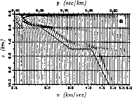
Figures 9 and 10 show
one of their examples.
sshead2
Figure 10
The result of downward continuation of the slant-stacked wavefield
at the top of Figure 9
with the correct velocity-depth function (the solid line).
(Clayton & McMechan)
|
|  |

Compare the method of Clayton and McMechan to that of Schultz.
Schultz flattens the reflections by a method
that is sensitive to the large p parts of the ellipse.
Clayton and McMechan look only at the largest p part of the ellipse.
Schultz has the advantage that a method based on reflection
is not troubled by high-velocity layers,
but the disadvantage that decision making is required during the descent.
Clayton and McMechan present the interpreter with a plane of information
from which the interpreter selects the velocity.
Clayton and McMechan's velocity space is a linear, invertible function
of the data.


Next: Slant stack and Fourier
Up: SLANT STACK
Previous: Interval velocities from slant
Stanford Exploration Project
10/31/1997

