Wave-Equation Migration

Prestack 3-D data are routinely imaged
by integrating the data over surfaces that
are determined by the Green functions between the source/receiver
locations at the surface and the image point at depth.
These methods, which are commonly referred as Kirchhoff migrations
(see
Chapter 2
in
3-D Seismic Imaging
),
are computationally efficient but have limitations when
imaging structures buried under complex overburden.
In these cases, the complexity of the velocity model
causes multipathing in the propagating wavefields,
and the integration surfaces are multivalued.
The numerical estimation of these multivalued surfaces
and the numerical integration of the data over them
can be cumbersome and prone to errors.
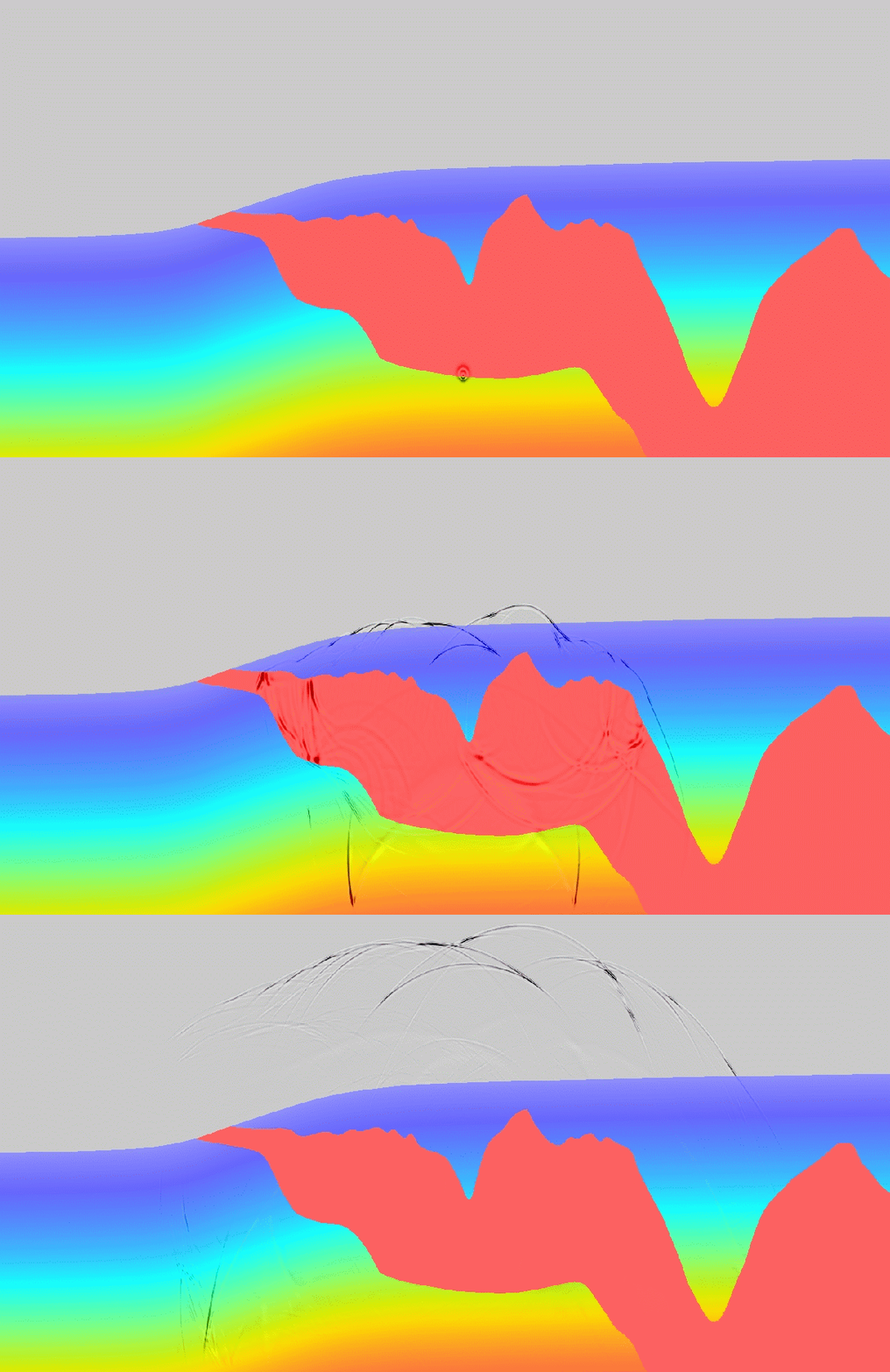
The images on the left illustrate one of these situations.
The color scale represents the velocity model
for a typical salt body in the Gulf of Mexico.
The contrast between the salt-body velocity
(4.5 km/s and represented by red in the image),
and the velocity of the surrounding sediments
(from about 2 km/s to about 3.5 km/s) is large.
Consequently, the wavefield generated by a source placed at the bottom
of the salt body is severely distorted, and when it reaches the surface
several of its branches carry significant seismic energy.
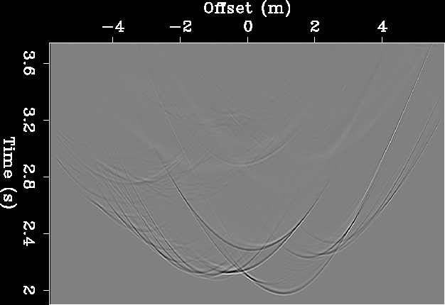
The gray-scale image shows the wavefield recorded at the surface,
and can be interpreted as the graphical representation of the Green functions
between the image point at depth and every point at the surface.
Clearly, the Green functions are multivalued, with several
branches having significant amplitudes and phase distortion.
To focus the data effectively
an imaging method must take properly into
account this complexity in the wave-propagation phenomena.
When the complexity of the velocity model makes Kirchhoff
methods ineffective,
wavefield-continuation migration methods,
also known as wave-equation migration methods,
are a valuable alternative to Kirchhoff methods
(see
Chapter 4
in
3-D Seismic Imaging
).
They naturally handle multipathing of the reflected energy
because the solution of the wave-equation is not computed
as a finite set of high-frequency arrivals but the whole
wavefield is propagated at each step of the wavefield-continuation process.
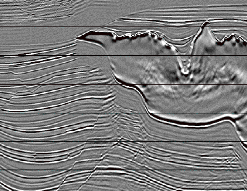
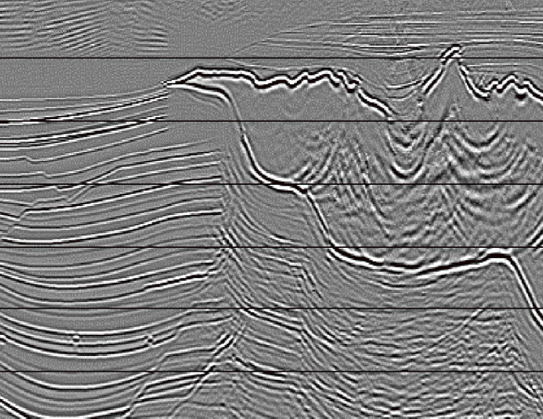
The images on the right compare the image obtained by a Kirchhoff
migration applied to the synthetic data set modeled over the salt body
shown above with the image obtained by a wave-equation migration
method from the same data
(Paffenholz, 2001).
Wave-equation migration has many challenges.
A crucial one is the computational cost, in particular for 3-D
prestack imaging.
A well-known method to reduce computationally cost
is to downward-continue the data in depth solving
the one-way wave-equation instead of propagating them in
time solving the full two-ways wave equation.
Chapter 5
in
3-D Seismic Imaging
provides an overview of the numerous downward-continuation
methods that have been developed since Jon Claerbout first introduced
downward-continuation migration in the early 70s.
For 3-D marine surveys further efficiency can be gained
by exploiting the narrow azimuthal range of data recorded
by marine vessels using
common-azimuth migration
or
plane wave-migration
(see
Chapter 7
in
3-D Seismic Imaging
).
Therefore, in several important situations
prestack wave-equation migration
has proven to be computationally competitive with Kirchhoff migration
and yield better images.
The main limitation of downward-continuation methods
is that they are intrinsically unable to handle events that propagate along
both directions of the extrapolation axis (i.e. depth),
such as overturned events.
This limitation may hamper the imaging of overhanging
structures, such as salt flanks, that are
illuminated by overturned reflections.
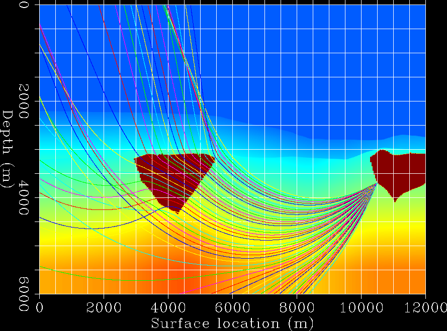
The image on the left shows a velocity slice taken
from real data set in West Africa.
The raypaths superimposed onto the velocity field
show that the flank of the salt body on the right
is illuminated by overturned events that propagate through the
salt body on the left.
The imaging of these events would likely benefit from
the use of a wave-equation algorithm,
but these events cannot be imaged by a simple downward-continuation migration.
These events could be imaged by using reverse time migration
(
Biondi and Shan, 2002
),
but reverse-time migration is more expensive than downward continuation
by at least one order of magnitude, it has problem with
artifacts related to reflections at sharp discontinuities
of the migration velocity model,
and, finally, to image data in
anisotropic media
it requires the solution of the full-elastic wave equation instead of
the much less computational intensive solution of the acoustic wave equation.
Shan and Biondi (2004)
are developing a promising method to address all these problems.
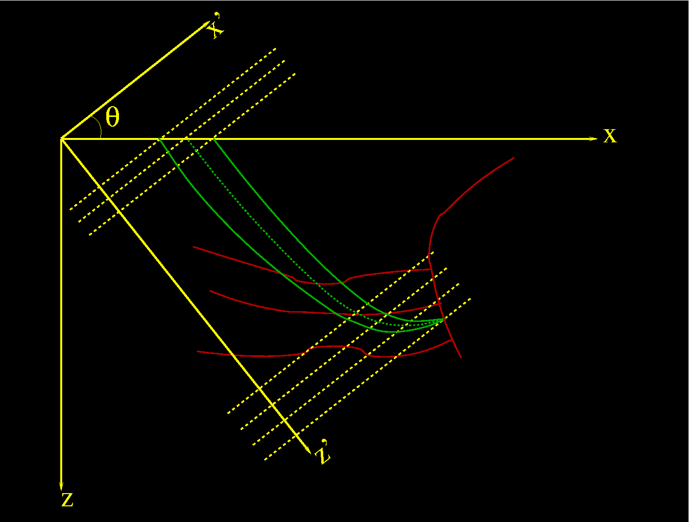
To assure that all reflections are correctly imaged,
independently from the dip and orientation of the reflectors,
the data are first preprocessed to synthesize shot gather
recorded by plane-wave sources instead of point sources.
Each plane-wave gather is then migrated using a coordinate system
tilted in the same direction as the propagation direction of the source plane wave.
The sketch below illustrates how this method can image overturned
events using the efficient and flexible one-way solution
of the scalar wave equation.
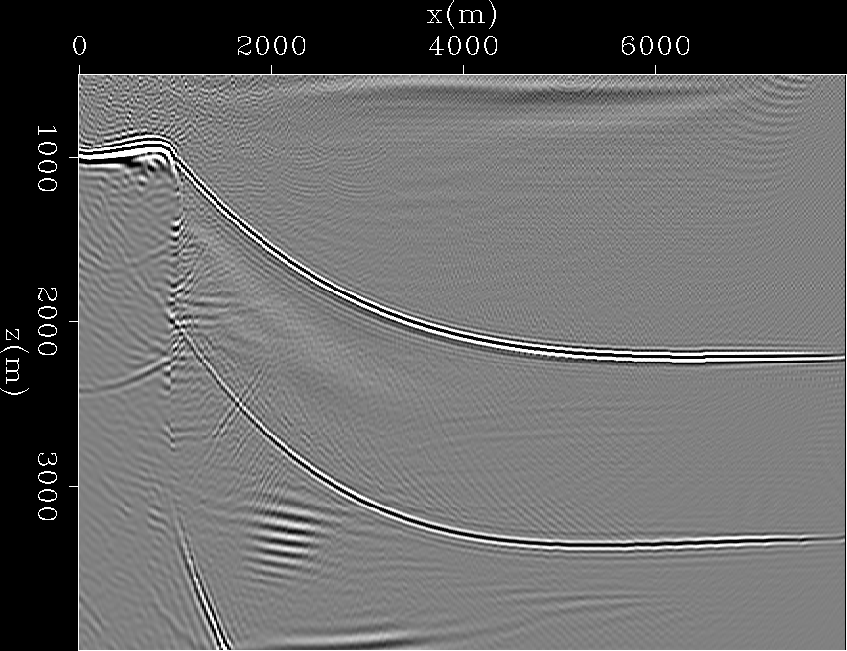
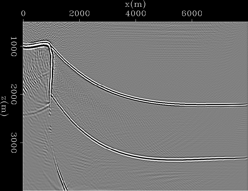
The two images below compare the result of plane-wave migration in tilted
coordinates with the result of plane-wave migration by simple
downward-continuation of a synthetic data set containing
overturned reflections from an overhanging salt flank.
Notice that the sedimentary layer between the first and second interfaces
was assumed to be anisotropic, and thus an anisotropic one-way extrapolator
was used in both cases.
However, simple downward continuation could not image the overhanging
part of the salt flank, that was on the contrary perfectly imaged by
the tilted-coordinates migration method.
