Bull's eyes analysis
Objectives
-
Take DMO/Calibrated-DMO/IZO into account in survey evaluation and design (SED)
-
Take DMO/Calibrated-DMO/IZO into account in real time on board quality
control
- Select IZO processing parameters (number of iterations, etc)
The method
Generate a synthetic data set in the real geometry and image the synthetic
data with alternative processing methods such as DMO, Calibrated-DMO, and
IZO, or with alternative parameters.
The economy is based on the fact that the results can be interpreted in the
frequency domain based on imaging just a few frequencies.
The earth model is arbitrary. We choose to have a single flat reflector
and a single or a few point diffractors. Such simple earth models are
complex enough to show a geometry footprint problem and are easy to
interpret (see below).
Example
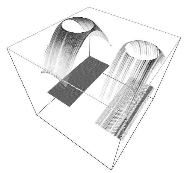
The zero offset cube for an point diffractor is a hyperboloid of revolution.
The flat reflector gives a flat event. In the following figure, IZO image
is on the left and DMO image is on the right.

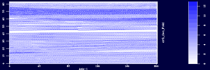
The geometry footprint, as described in the next fold map (taken from the
marine data example
) superimposes the hyperboloid and on the flat reflector.
It shows much more strongly on the DMO image on the right.
Time slices through the hyperboloid are circles.
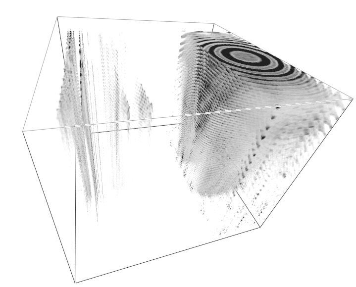
Frequency slices are Bull's Eyes due to the interference between
the hyperboloid and the flat reflector.
Here, DMO is on the left and IZO on the right.
The acquisition footprint overwhelms the DMO image on the left so
the Bull's eyes do not show in this figure. The Bull's eyes
are visible on the IZO image on the right.
Comparing different processing methods, NMO, DMO, and IZO,
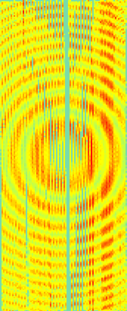
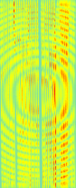
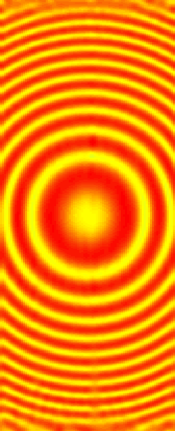
we see that for this geometry only IZO gives an image free of geometry
footprint.
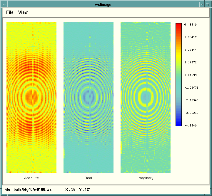
At higher frequencies, neither DMO nor IZO gives a good image.
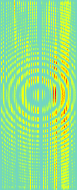
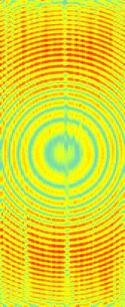
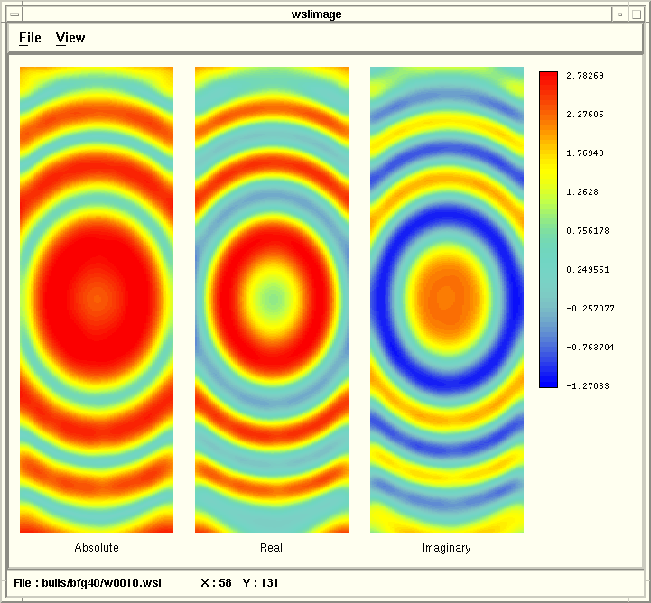
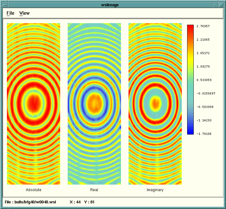
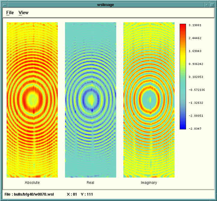
Following is a comparison of different frequencies (all processed with IZO)
showing the different bull's eyes for frequencies 10, 40, 70, and 100.
For each frequency, the absolute value, the real, and the imaginary parts
of the complex frequency slice are shown side by side.
Next the effect of a processing parameter is shown of the Bull's eyes.
For example, the smoothing factor parameter shows the effect of under
smoothing (0.25)
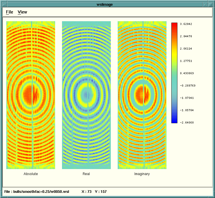
under smoothing allows wave-numbers which are too high for a wave field.
The default (0.5)
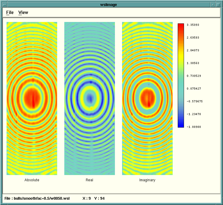
and over-smoothing (1 and 2)
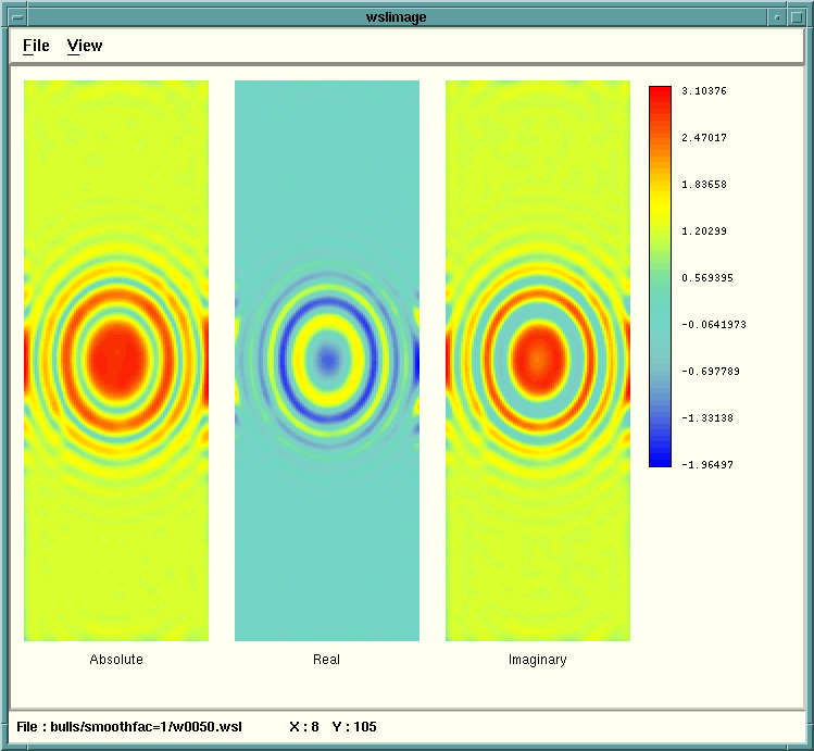

Over smoothing causes attenuation of higher wave-numbers and
loss of dipping events.


