 |
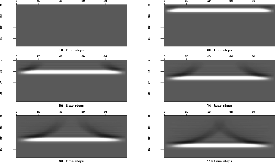
Figure 6 Snapshots of a plane wave before well production. A plane wave propagates unperturbed through the reservoir before the well production commences. The velocity field is constant.
I implemented a simple acoustic wave simulator. An elastic wave simulator (which I chose not to implement) would be able to compute Gassmann's compressional and shear waves. Furthermore, such an elastic wave simulator would have nicely corresponded with the more sophisticated rock physics and reservoir flow considerations discussed in this paper. Alas, I did not have the time to implement the more complex operator. The simpler acoustic simulator may thrive nicely with my simple reservoir flow simulator. Furthermore, acoustic wave propagation has been surprisingly successful in traditional seismic processing.
The input to the wave simulator is a single velocity field. In this first draft, I derive the velocity field independent of the underlying rock physics considerations discussed here. I simply choose a constant base velocity and add a scaled version of the pressure field computed by the reservoir simulator. This approach assumes the velocity variation to be linearly dependent on reservoir pressure.
The wavefield source is a plane wave (Ricker wavelet) that initially originates at the northern edge of the reservoir. To simulate a more realistic seismic field experiment, I would use a series of point sources and extract from the complete wavefield time traces at specific geophone locations.
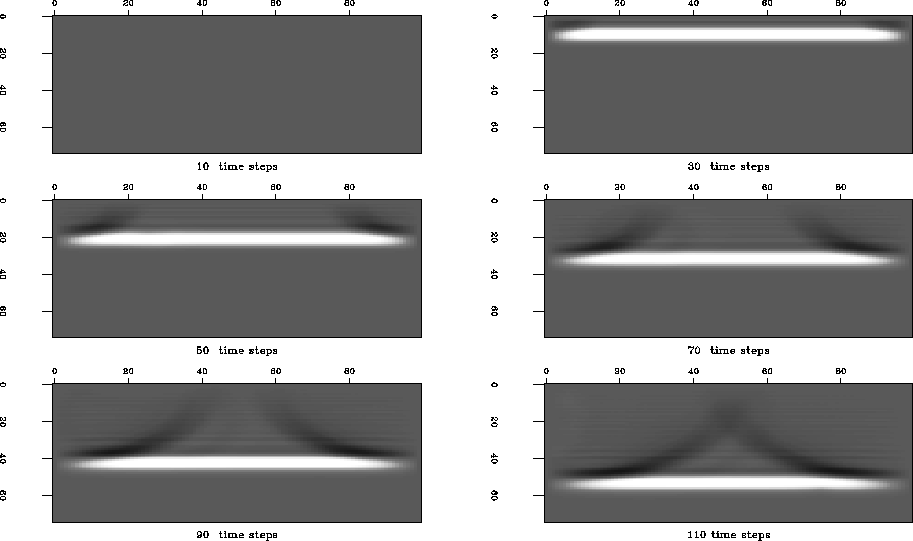
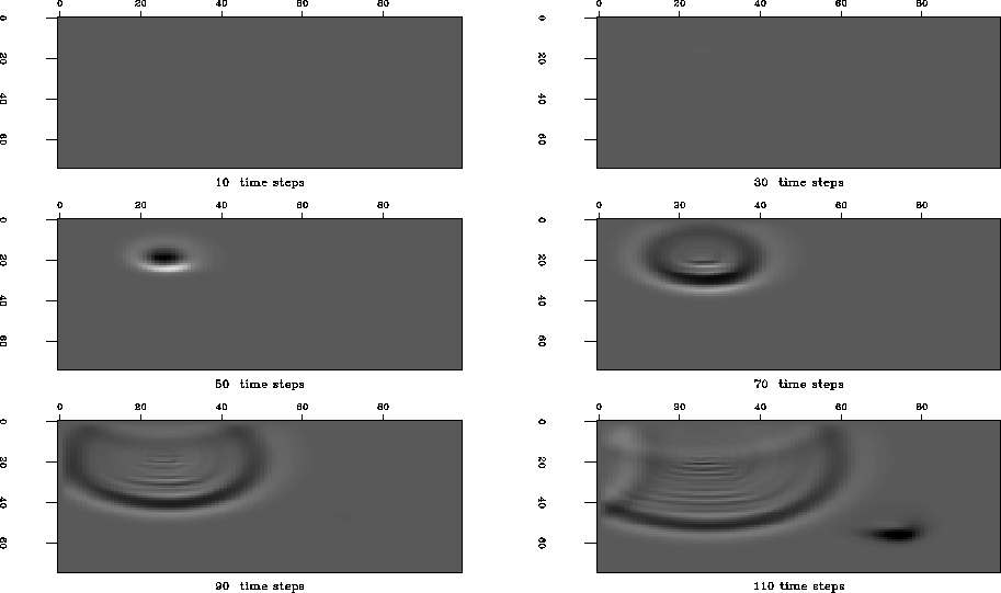
The first sesimic wavefield recorded over the initial reservoir, Figure 6, and the later wavefield recorded over an altered reservoir, Figure 7, show no apparent difference. The wavefield is dominated by the large amplitude of the direct wave. However, the difference of the two wavefields, Figure 8, reveals the secondary wavefield due to the scattering effect of the altered fluid contents of the rock adjacent to the two wells.
 |
 |
 |