 |
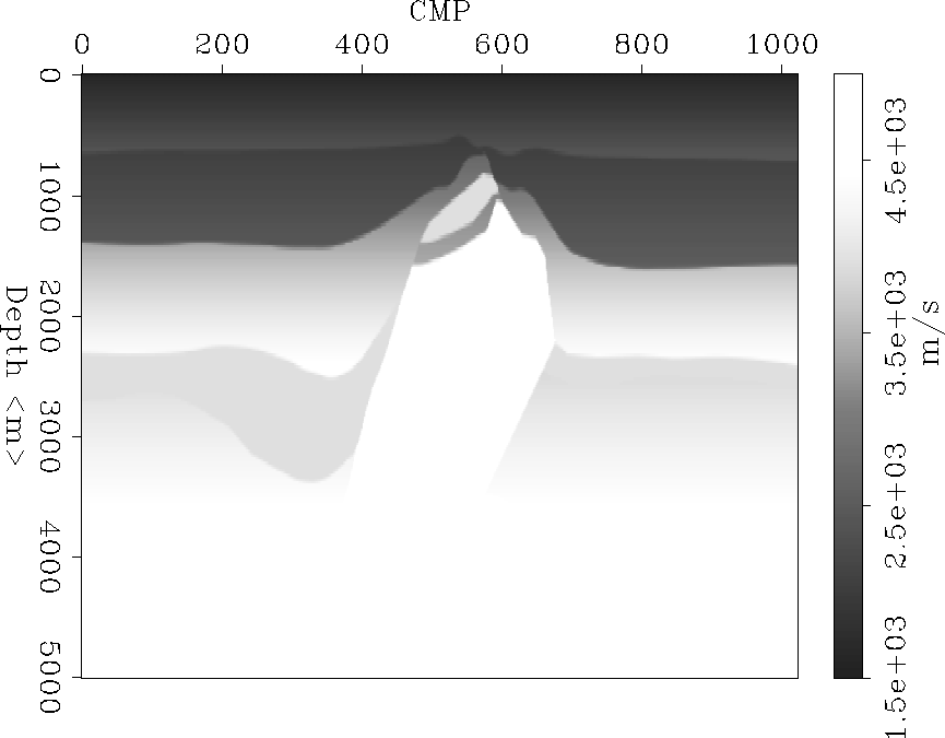
Figure 1 Depth velocity model.
In order to show the implementation of the basic tools for depth focusing analysis for a 3-D data set, we present some preliminary results with two differents data set: a 2-D synthetic data set of a salt diapire, and a 3-D data set from the North sea. The depth error gathers were obtained by using a prestack downward-continuation operator in common-azimuth, based on the stationary-phase approximation of the 3-D DSR. This approximation reduces the dimensionality of the downward-continuation operator from 5 to 4 dimensions, constraining the direction of propagation of source and receiver rays to the same plane and azimuth Biondi and Palacharla (1996).
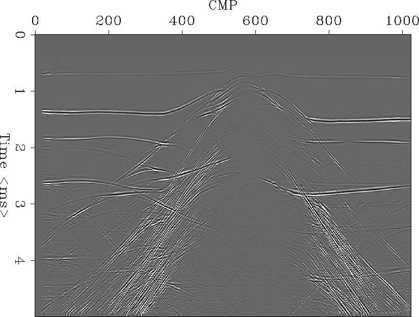
The synthetic data set is the result of a finite-difference modeling of the synthetic model based on a geologic structure due to the rise of a salt diapire (Figure 1). This geologic model is characterized by a strong lateral velocity gradient in the cable length. Figure 2 shows the near-offset section result of the seismic modeling of this geologic structure. This synthetic data set have the following acquisition parameters: source spacing 50m; receiver spacing 25m; final CMP spacing 12.5m; near-offset 170m; far-offset 3350m; maximum recorded time 5s; and time sampling 4ms.
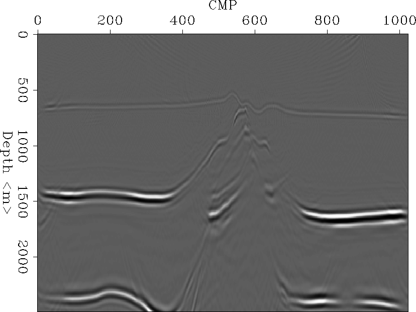
Figure 3 plots a prestack depth migration with 90% of the real velocity model (Figure 6). The final depth of this migrated depth section is 2500m in order to analyze the focusing condition of the shallow events through the depth error gathers show in Figures 4 and 5.
To migrate this data set with the 2-D prestack depth migration operator version of the 3-D common-azimuth operator, we defined 5 reference velocities (which kept constant) and an interval velocity model. Figures 4 and 5 show a cube of depth error gather where the lateral cube face represents a focal section resulting from choosing a specific depth error, in this case zero error. Changing the depth error plane (i.e. constant error surface) for a surface that follows the maximum focusing conditions in the depth error gathers, the resulting focal image would be the best. In this example the focal image is under-sampled in the CMP-domain because we saved the depth error gathers every ten CMP. In contrast, the top face of the cube in figure (4) is a depth slice that makes picking more easy in areas where the depth error gathers are difficult to interpret.
Figure 5 shows four different depth error gathers for the CMPs 15, 600, 700, and 1000. The lateral dispersion shown in a depth error anomaly is associated with the salt dome velocity complexity. Picking the depth error values at the maximum amplitude condition and using the equations 3 and 4, it is possible to update the velocity field. At this time we are working to develop the programs to update the interval velocity field.
 |
 |
 |
 |
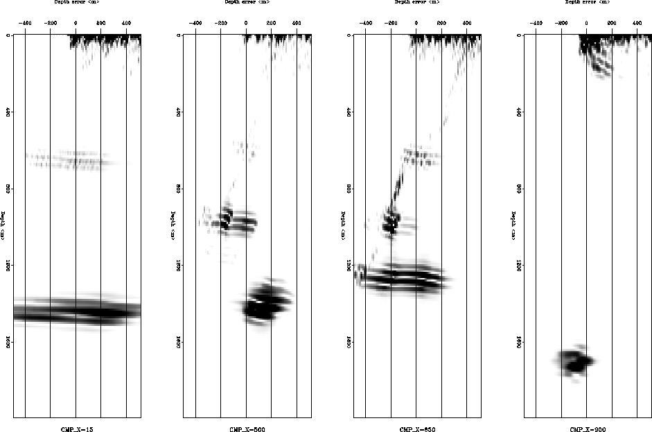 |
Figure 6 shows the velocity field in CMP domain for cross-line coordinate 19450m of a 3-D data set from the North Sea. This is characterized by a strong lateral and vertical velocity gradients due to geologic process. This 3-D marine data set has a CMP spacing of 9.375m in the in-line direction, 25m in the cross-line direction, and the far-offset is 2200m. Azimuth-moveout (AMO) transformation was applied to the data in order to apply an azimuth rotation over the data to obtain an effective common-azimuth data set for the 3D common-azimuth migration Biondi (1997).
 |
 |
This 3-D marine date set have been imaged successfully using common- azimuth migration Biondi (1997). Our goal is to update the velocity field in areas with focusing problems and show these problems using the depth error gathers. Future work will show more than one velocity analysis iteration because at present we are developing the codes for the interpolation of the velocities estimated on a CMP location.
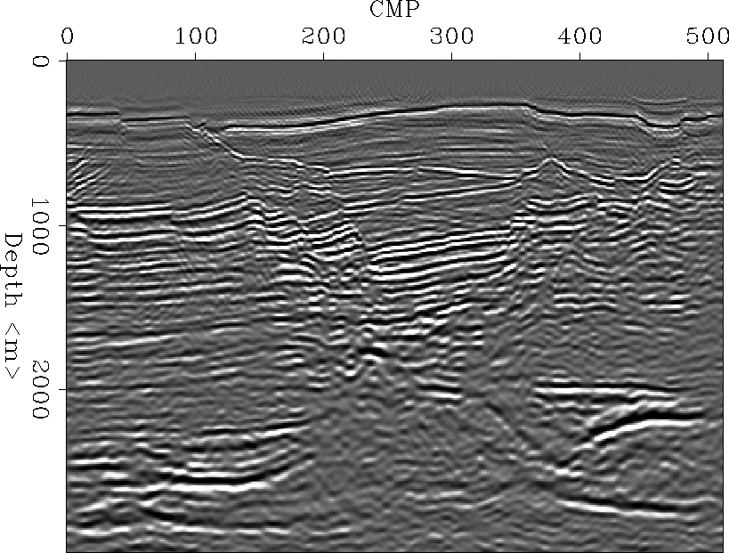
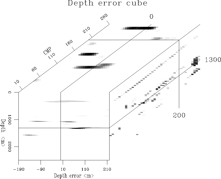
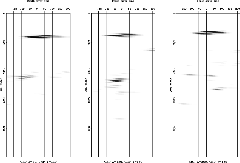
Figure 7 shows a 3-D prestack depth migrated image using the best velocity field available. This migrated in-line section is located in the cross-line position 19450m. During the 3-D migration we saved the zero-offset trace for every depth step and every 10 CMP in order to obtain the depth error gather plotted in Figures 8 and 9. In those figures the depth error gathers are plotted for a final depth of 2000m, with the object to analyze the focusing condition of the shallow migration velocity. It is observed that the focusing condition is lateral shifted to positive error, implying a lower migration velocity velocity (CDP:500 and 650).
In order to help the interpretation of the depth error gathers in complex areas, we plotted the depth error gathers using 3-D graphic tools (Rickmovie, a SEPLib tool). In this way the picking of a maximum in amplitude can be easily checked through the focal image (lateral plane: CMP-depth plane for a constant depth error) or by a depth slice of the depth error cube (see Fig. 8). Analyzing the depth error gathers plotted in figures 8 and 9, it can be seen that the seismic event blow a 1000m has a depth error associated with a high migration velocity in the CDP 50. In contrast, the migration velocity at depth of 1000m needs to be decrease in the zone close to the CDP 200. This shallow velocity error affecting is the image of a deeper horizons, like one at 1350m depth.
 |
 |