

Next: Experiments
Up: FINITE-DIFFERENCE MODELING
Previous: FINITE-DIFFERENCE MODELING
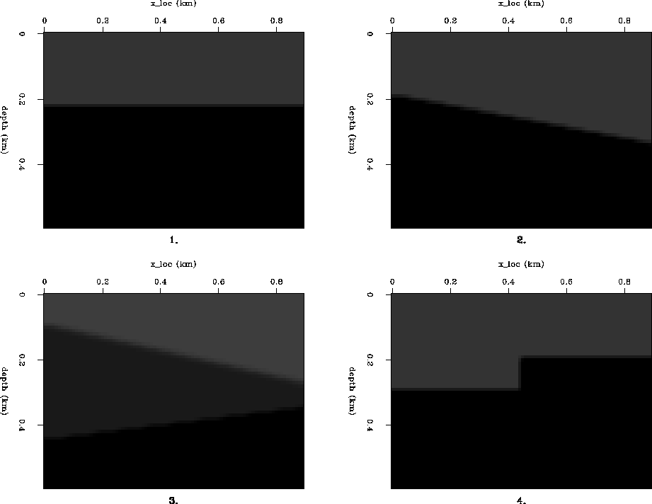
Four different Earth models were constructed (Figure 4):
- 1.
- A simple horizontal plane layer
- 2.
- A dipping plane layer
- 3.
- Two plane layers with opposite dips
- 4.
- A faulted block model
models
Figure 4
Models for finite-difference experiments: 1. Simple plane layer,
2. Single dipping layer, 3. Two dipping layers, and 4. Fault model.
All axes show km's. Velocities vary from 1500 m/s in the uppermost
layer to 2000 m/s in the half-space below.


The velocities in each model varied from 1500 m/s in the uppermost
layer to 2000 m/s in the half-space below. The density values were
engineered artificially to give large impedance contrasts at the
boundaries and hence strong reflections. In all cases the top boundary
was a free surface.
The simulations were done using a versatile finite-difference modeling
program written by Martin Karrenbach 1995. A cell size
of 5 m by 5 m were used, with time-steps of 2 ms. The input grids
were surrounded by an
exponential damping boundary that was 20 cells wide, and a
one-way boundary, 4 cells wide. To reduce artifacts due to the
discrete nature of the mesh, the models were slightly smoothed. This
can be seen in Figure 4.


Next: Experiments
Up: FINITE-DIFFERENCE MODELING
Previous: FINITE-DIFFERENCE MODELING
Stanford Exploration Project
11/11/1997
