We define AMO as an operator that transforms 3-D prestack data with a given offset and azimuth to equivalent data with different offset and azimuth. To derive the AMO operator we collapse in one single step the cascade of an imaging operator and a forward modeling operator. In principle, any 3-D prestack imaging operator can be used for defining AMO. We initially cascaded DMO and ``inverse'' DMO, but, to derive an accurate expression for the spatial aperture of AMO, we had to use full 3-D prestack constant velocity migration and its inverse. As expected, the kinematics of AMO, as defined after NMO, are independent from its derivation.
AMO is not a single-trace to single-trace transformation, but it is a
partial-migration operator that moves events across midpoints
according to their dip. Its impulse response is a saddle in the
output's midpoint domain. The shape of the saddle depends on the offset
vector of the input data
![]() and on the offset vector of the desired output data
and on the offset vector of the desired output data
![]() ,
where the unit vectors
,
where the unit vectors ![]() and
and
![]() point respectively in the in-line direction and the cross-line
direction. The time shift to be applied to the data is a function of
the difference vector
point respectively in the in-line direction and the cross-line
direction. The time shift to be applied to the data is a function of
the difference vector
![]() between the midpoint of the input trace and the
midpoint of the output trace.
The analytical expression of the AMO saddle, as we derive it in
Appendices A and B, is,
between the midpoint of the input trace and the
midpoint of the output trace.
The analytical expression of the AMO saddle, as we derive it in
Appendices A and B, is,
| |
(1) |
The surface represented by equation (1) is a skewed
saddle; its shape and spatial extent are controlled by the values of
the absolute offsets h1 and h2, and by the azimuth
rotation ![]() . Consistent with intuition,
the spatial extent of the operator has a maximum for rotation of 90
degrees, and it vanishes when offsets and azimuth rotation tend to zero.
Furthermore, it can be easily verified that t2= t1 for the
zero-dip components of the data; that is, the kinematics of zero-dip
data after NMO do not depend on azimuth and offset.
Figure
. Consistent with intuition,
the spatial extent of the operator has a maximum for rotation of 90
degrees, and it vanishes when offsets and azimuth rotation tend to zero.
Furthermore, it can be easily verified that t2= t1 for the
zero-dip components of the data; that is, the kinematics of zero-dip
data after NMO do not depend on azimuth and offset.
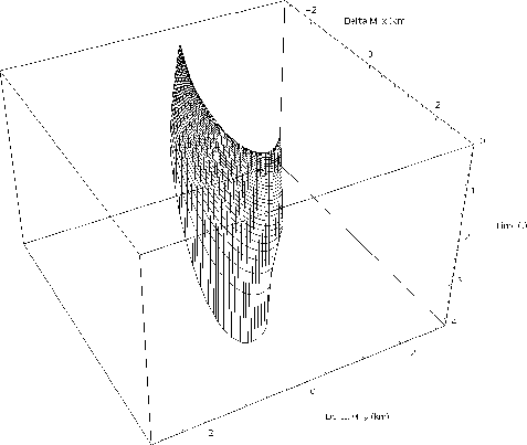
Figure ![[*]](http://sepwww.stanford.edu/latex2html/cross_ref_motif.gif) shows the surface of the AMO
impulse response when t1 is equal to 1 s, h1 is
equal to 2 km, h2 is equal to 1.8 km,
shows the surface of the AMO
impulse response when t1 is equal to 1 s, h1 is
equal to 2 km, h2 is equal to 1.8 km,
![]() is equal to zero degrees, and
is equal to zero degrees, and ![]() is equal to 30
degrees.
is equal to 30
degrees.
 |
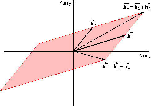
The expression for the kinematics is velocity independent, but the lateral aperture of the operator does depend on velocity. An upper bound on the spatial extent of the AMO operator is defined by the region where the expression in equation (1) is valid. Equation (1) becomes singular when either of the following conditions are fulfilled
 |
||
| (2) |
![[*]](http://sepwww.stanford.edu/latex2html/cross_ref_motif.gif) shows an example parallelogram
that represents the maximum possible spatial extent of the AMO
operator. In appendix C we derive more stringent bounds for the AMO aperture,
that are, for given
shows an example parallelogram
that represents the maximum possible spatial extent of the AMO
operator. In appendix C we derive more stringent bounds for the AMO aperture,
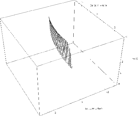
that are, for given ![[*]](http://sepwww.stanford.edu/latex2html/cross_ref_motif.gif) is thus the worse
case, when either the velocity or the input traveltime is equal to
zero. Figure
is thus the worse
case, when either the velocity or the input traveltime is equal to
zero. Figure ![[*]](http://sepwww.stanford.edu/latex2html/cross_ref_motif.gif) shows the effective AMO
impulse response when the velocity-dependent aperture limitation,
corresponding to a realistic minimum velocity of 2
shows the effective AMO
impulse response when the velocity-dependent aperture limitation,
corresponding to a realistic minimum velocity of 2 ![[*]](http://sepwww.stanford.edu/latex2html/cross_ref_motif.gif) .
The surface shown in
Figure
.
The surface shown in
Figure ![[*]](http://sepwww.stanford.edu/latex2html/cross_ref_motif.gif) is significantly narrower than the
whole impulse response shown in Figure
is significantly narrower than the
whole impulse response shown in Figure ![[*]](http://sepwww.stanford.edu/latex2html/cross_ref_motif.gif) .
This velocity-dependent aperture limitation is important for an
efficient use of AMO and it contributes to make the cost of applying
AMO to the data negligible compared to the cost of applying
a full 3-D prestack migration.
.
This velocity-dependent aperture limitation is important for an
efficient use of AMO and it contributes to make the cost of applying
AMO to the data negligible compared to the cost of applying
a full 3-D prestack migration.
 |
 |
The effective aperture becomes tiny when the azimuth rotation
![]() is small. At the limit, the expression in
equation (1) is singular when the azimuth rotation
vanishes and the AMO surface reduces to a 2-D line. This operator,
corresponding to the case of offset continuation
Bolondi et al. (1984), has been derived independently by Biondi and
Chemingui 1994, Stovas and Fomel
1996, and (in a different form) Bagaini et
al. 1994. Its expression is given by the
following quadric equation,
is small. At the limit, the expression in
equation (1) is singular when the azimuth rotation
vanishes and the AMO surface reduces to a 2-D line. This operator,
corresponding to the case of offset continuation
Bolondi et al. (1984), has been derived independently by Biondi and
Chemingui 1994, Stovas and Fomel
1996, and (in a different form) Bagaini et
al. 1994. Its expression is given by the
following quadric equation,
![\begin{eqnarray}
\lefteqn{{t}_{2}(\Delta m,h_{1},h_{2},{t}_{1})=} \nonumber \\ &...
...[(h_{1}+h_{2})^2-\Delta m^2]}}}
{\sqrt{2}h_{2}} & h_{2}\leq h_{1}.\end{eqnarray}](img26.gif) |
||
| (3) |
While the kinematics of AMO are independent from its derivation, the amplitude term varies according to the derivation. We present, and used for the AMO applications shown in this paper, the AMO amplitude that is related to Zhang-Black DMO. It can be shown that the choice of the Zhang-Black's Jacobian yields an amplitude-preserving AMO operator, at least when applied on regularly sampled common offset-azimuth cubes Chemingui and Biondi (1995). This particular choice of the Jacobian results into the following expression for the amplitude term,
 |
||
| (4) |
Notice that the frequency ![]() enters as
multiplicative factor in the expression for AMO amplitudes.
This term can be applied
to the output data
in the time domain
by cascading a causal half-differentiator with
an anti-causal half-differentiator.
enters as
multiplicative factor in the expression for AMO amplitudes.
This term can be applied
to the output data
in the time domain
by cascading a causal half-differentiator with
an anti-causal half-differentiator.