|
rayab3D
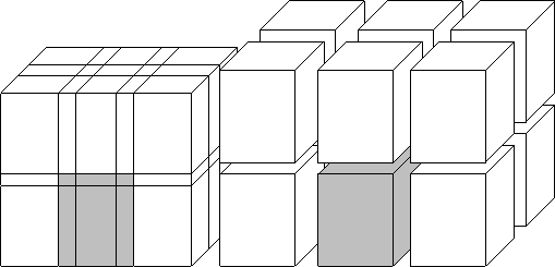
Figure 1 Left is the data input and output volume. Right is the data structure during analysis. |  |
To estimate and remove the local plane reflector component, we split the non-stationary seismic image into small local stationary cubes (see Figure 1). In each subcube, a filter step independently estimates and removes the plane reflector component. The filter output, those events the filter could not remove, are ultimately merged into an image volume of the same size as the original unfiltered image.
|
rayab3D
Figure 1 Left is the data input and output volume. Right is the data structure during analysis. |  |
The choice of the subcube's size depends on the non-stationarity of the processed image. A very large subcube would probably not fit the model of a single plane reflector (just as a large curve segment is probably not well approximated by a straight-line segment). In contrast, a very small subcube would probably not permit a reliable estimate of the local reflector component. Ideally the subcube size should depend on the local stationarity of an image. We, however, used existing routines for splitting and merging the imageClaerbout (1994). These routines require the user to specify a single, general subcube size which is applied equally to the entire image. We typically chose subcubes of the size (n1,n2,n3) = (15,8,8), where n1 refers to the number of samples in the depth or time dimension, and n2, n3 to the number of samples in the two horizontal dimensions. We overlapped the subcubes by 50%. We have not discovered any artifacts introduced into the processed figures by the software that splits and merges the data.