![[*]](http://sepwww.stanford.edu/latex2html/cross_ref_motif.gif) ,
that has a syncline reflector under an undulating surface.
The irregular surface is modeled to have
not only gradual topographic changes,
but also discontinuity.
,
that has a syncline reflector under an undulating surface.
The irregular surface is modeled to have
not only gradual topographic changes,
but also discontinuity.
I test the datuming scheme described above with
phase-shift, split-step, and finite-difference
depth extrapolation algorithms.
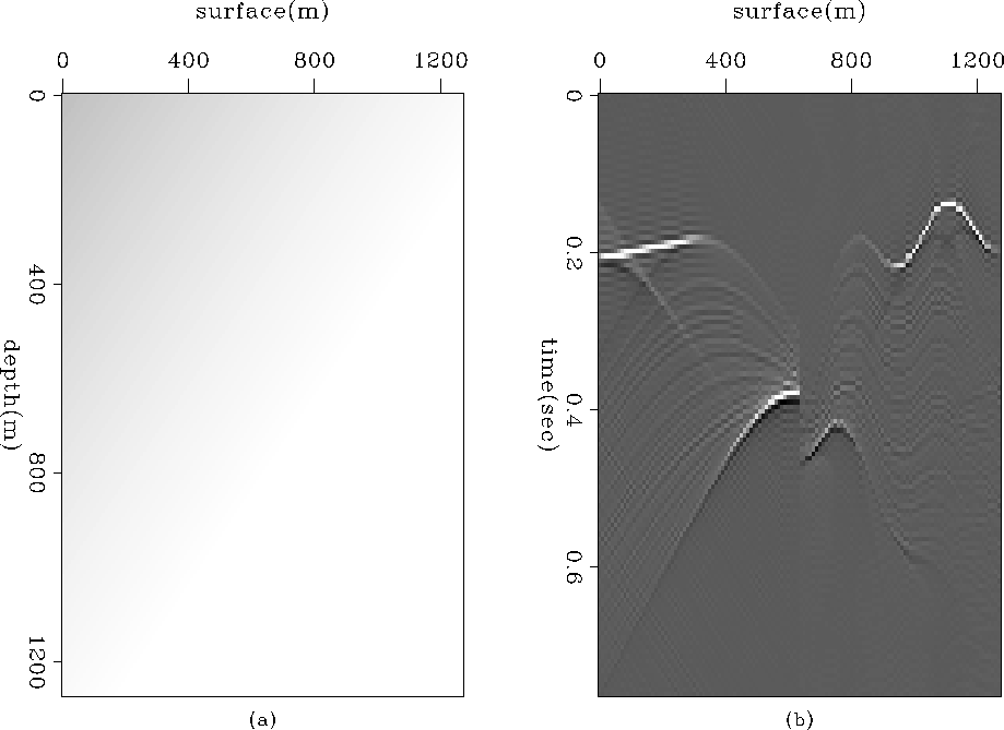
For testing, I use a simple model, Figure ![[*]](http://sepwww.stanford.edu/latex2html/cross_ref_motif.gif) ,
that has a syncline reflector under an undulating surface.
The irregular surface is modeled to have
not only gradual topographic changes,
but also discontinuity.
,
that has a syncline reflector under an undulating surface.
The irregular surface is modeled to have
not only gradual topographic changes,
but also discontinuity.
 |
 |
The forward modeling experiment was done
using the algorithm explained in Figure ![[*]](http://sepwww.stanford.edu/latex2html/cross_ref_motif.gif) for a constant velocity; Figure
for a constant velocity; Figure ![[*]](http://sepwww.stanford.edu/latex2html/cross_ref_motif.gif) (a) shows the result.
Datuming was then performed using
the algorithm shown in Figure
(a) shows the result.
Datuming was then performed using
the algorithm shown in Figure ![[*]](http://sepwww.stanford.edu/latex2html/cross_ref_motif.gif) with the phase-shift extrapolation
as the depth extrapolation operator W.
The result appears in Figure
with the phase-shift extrapolation
as the depth extrapolation operator W.
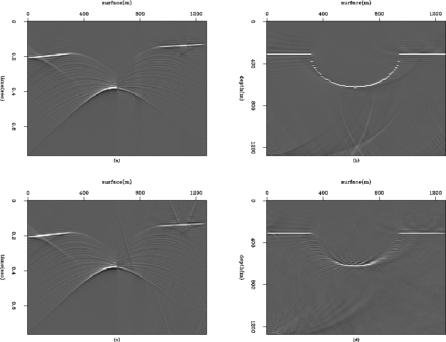
The result appears in Figure ![[*]](http://sepwww.stanford.edu/latex2html/cross_ref_motif.gif) (b);
the exact bow-tie shaped wave field is
the characteristic of the syncline reflector on a flat datum.
I then applied the same algorithm
with the other depth extrapolation schemes.
Figures
(b);
the exact bow-tie shaped wave field is
the characteristic of the syncline reflector on a flat datum.
I then applied the same algorithm
with the other depth extrapolation schemes.
Figures ![[*]](http://sepwww.stanford.edu/latex2html/cross_ref_motif.gif) (c) and (d) show the datumed
results for the split-step and
the 45-degree finite-difference methods.
When the velocity is constant, the split-step algorithm
is identical to the phase-shift algorithm.
Therefore, we can see that the datumed wave fields
in Figures
(c) and (d) show the datumed
results for the split-step and
the 45-degree finite-difference methods.
When the velocity is constant, the split-step algorithm
is identical to the phase-shift algorithm.
Therefore, we can see that the datumed wave fields
in Figures ![[*]](http://sepwww.stanford.edu/latex2html/cross_ref_motif.gif) (b) and (c) are the same.
The result of the finite-difference method,
Figure
(b) and (c) are the same.
The result of the finite-difference method,
Figure ![[*]](http://sepwww.stanford.edu/latex2html/cross_ref_motif.gif) (d), also shows a correctly-located
bow-tie shaped wave field
with remaining very weak artifacts
in the region under the undulating surface.
These artifacts can be explained
as the energy from the evanescent region
that has not been removed.
(d), also shows a correctly-located
bow-tie shaped wave field
with remaining very weak artifacts
in the region under the undulating surface.
These artifacts can be explained
as the energy from the evanescent region
that has not been removed.
To illustrate the effectiveness of the datuming algorithm,
I tested a velocity function that varies in depth and lateral extent
for the same reflector and topographic model
shown in Figure ![[*]](http://sepwww.stanford.edu/latex2html/cross_ref_motif.gif) .
The velocity model used in this experiment
has a linear increase both in depth and lateral:
v(x,z)=1500.+0.2x+0.2z (Figure
.
The velocity model used in this experiment
has a linear increase both in depth and lateral:
v(x,z)=1500.+0.2x+0.2z (Figure ![[*]](http://sepwww.stanford.edu/latex2html/cross_ref_motif.gif) (a)).
The zero-offset data are modeled
with the use of split-step extrapolation;
Figure
(a)).
The zero-offset data are modeled
with the use of split-step extrapolation;
Figure ![[*]](http://sepwww.stanford.edu/latex2html/cross_ref_motif.gif) (b) shows the result.
The datuming algorithm is then applied to the data,
Figure
(b) shows the result.
The datuming algorithm is then applied to the data,
Figure ![[*]](http://sepwww.stanford.edu/latex2html/cross_ref_motif.gif) (b), using the split-step extrapolation;
the result is shown in Figure
(b), using the split-step extrapolation;
the result is shown in Figure ![[*]](http://sepwww.stanford.edu/latex2html/cross_ref_motif.gif) (a).
Figure
(a).
Figure ![[*]](http://sepwww.stanford.edu/latex2html/cross_ref_motif.gif) (b) shows the migrated image.
By comparing Figure
(b) shows the migrated image.
By comparing Figure ![[*]](http://sepwww.stanford.edu/latex2html/cross_ref_motif.gif) and Figure
and Figure ![[*]](http://sepwww.stanford.edu/latex2html/cross_ref_motif.gif) (b),
we can see the effect of the datuming algorithm.
The datuming algorithm using the finite-difference extrapolation
is also tested for the same data, shown in Figure
(b),
we can see the effect of the datuming algorithm.
The datuming algorithm using the finite-difference extrapolation
is also tested for the same data, shown in Figure ![[*]](http://sepwww.stanford.edu/latex2html/cross_ref_motif.gif) (b);
the datumed wave field is shown in Figure
(b);
the datumed wave field is shown in Figure ![[*]](http://sepwww.stanford.edu/latex2html/cross_ref_motif.gif) (c)
and the migrated image is shown in Figure
(c)
and the migrated image is shown in Figure ![[*]](http://sepwww.stanford.edu/latex2html/cross_ref_motif.gif) (d).
In Figure
(d).
In Figure ![[*]](http://sepwww.stanford.edu/latex2html/cross_ref_motif.gif) (d)
we can see that the reflector is imaged correctly
with the exception of the steep dip portion, which is
limited by the 45-degree wave equation.
(d)
we can see that the reflector is imaged correctly
with the exception of the steep dip portion, which is
limited by the 45-degree wave equation.