![[*]](http://sepwww.stanford.edu/latex2html/cross_ref_motif.gif) ) was then obtained using
the composite indicator:
) was then obtained using
the composite indicator:
Thirty-one plane waves are synthesized with incidence angles that varys from -30 degrees to +30 degrees, in order to retrieve the angle-dependent reflectivity. For obtaining common incidence angle image section, I chose twenty-one depth levels for datum planes to synthesize the plane-wave with the corresponding incidence angle, and I extracted and patched the portions of the image near the datum planes to produce the common incidence angle image section.
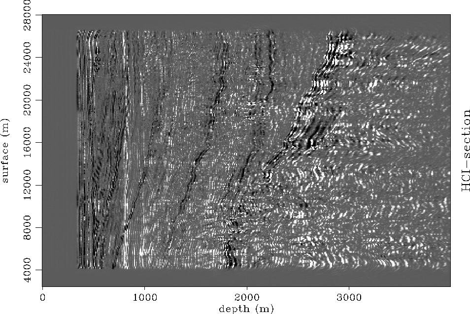
In order to show the global AVO trend of the subsurface,
a hydrocarbon indicator (HCI) section Lumley et al. (1995)
was computed using near and far incidence angle reflectivity amplitudes.
The angle-dependent reflectivity images were partially stacked
into two reflection-angle ranges: 0-15 degrees, and 15-30.
Call these two parameter sections ``near" N and ``far" F.
A reasonable HCI section (Figure ![[*]](http://sepwww.stanford.edu/latex2html/cross_ref_motif.gif) ) was then obtained using
the composite indicator:
) was then obtained using
the composite indicator:
| HCI = N(N-F) | (54) |
This N,F technique does not contain as much AVO information as impedance contrast sections, but has a higher S/N ratio.
 |