![[*]](http://sepwww.stanford.edu/latex2html/cross_ref_motif.gif) a.
Figure
a.
Figure ![[*]](http://sepwww.stanford.edu/latex2html/cross_ref_motif.gif) b displays the simulated seismic response of one
shot record and shows the AVO effect clearly.
b displays the simulated seismic response of one
shot record and shows the AVO effect clearly.
For the purposes of the comparison,
let us consider the simple acoustic subsurface model
shown in Figure ![[*]](http://sepwww.stanford.edu/latex2html/cross_ref_motif.gif) a.
Figure
a.
Figure ![[*]](http://sepwww.stanford.edu/latex2html/cross_ref_motif.gif) b displays the simulated seismic response of one
shot record and shows the AVO effect clearly.
b displays the simulated seismic response of one
shot record and shows the AVO effect clearly.
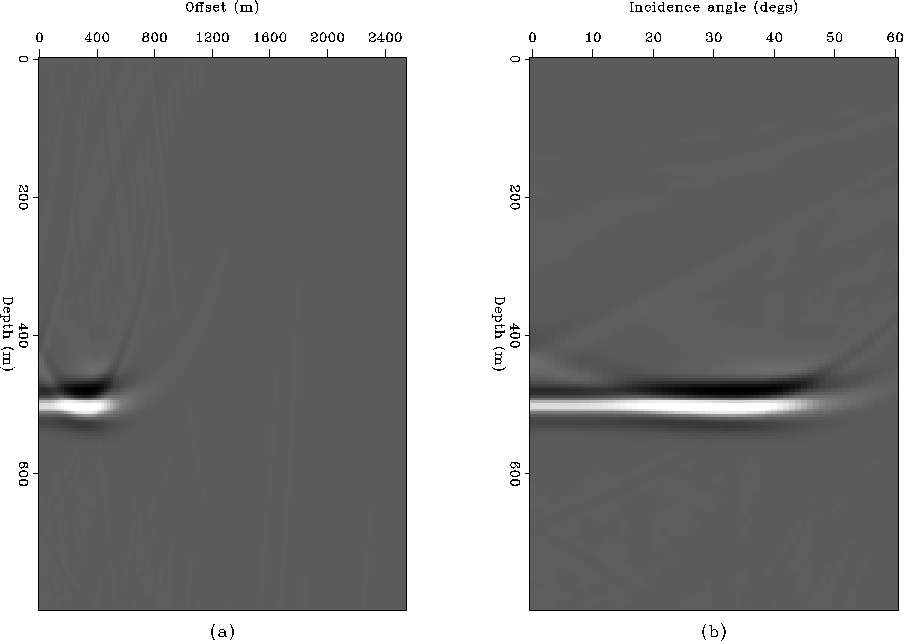
To obtain the angle-dependent reflectivity
with conventional prestack imaging,
I applied shot profile imaging with phase-shift extrapolation,
acquired the offset-dependent reflectivity image (Figure ![[*]](http://sepwww.stanford.edu/latex2html/cross_ref_motif.gif) a),
and transformed it to an angle-dependent reflectivity image
(Figure
a),
and transformed it to an angle-dependent reflectivity image
(Figure ![[*]](http://sepwww.stanford.edu/latex2html/cross_ref_motif.gif) b) using the incidence angle at each depth location.
Figure
b) using the incidence angle at each depth location.
Figure ![[*]](http://sepwww.stanford.edu/latex2html/cross_ref_motif.gif) shows an angle-dependent reflectivity
image obtained using de Bruin's imaging condition and
Figure
shows an angle-dependent reflectivity
image obtained using de Bruin's imaging condition and
Figure ![[*]](http://sepwww.stanford.edu/latex2html/cross_ref_motif.gif) , one obtained using
plane wave synthesis imaging.
All of them retrieve the general amplitude's increasing pattern
with respect to the incidence angle.
, one obtained using
plane wave synthesis imaging.
All of them retrieve the general amplitude's increasing pattern
with respect to the incidence angle.
To see the amplitude more clearly, I picked the amplitude
of each reflectivity image at the reflector depth
and plotted the amplitude as a function of the incidence angles
(Figure ![[*]](http://sepwww.stanford.edu/latex2html/cross_ref_motif.gif) ).
The comparison shows that the reflectivity obtained
by the plane wave synthesis is closer to the theoretical solution.
).
The comparison shows that the reflectivity obtained
by the plane wave synthesis is closer to the theoretical solution.
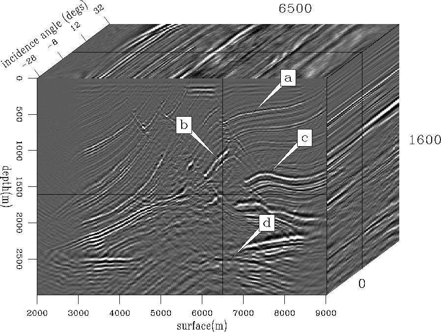
For a more realistic example, the Marmousi dataset was tested.
Figure ![[*]](http://sepwww.stanford.edu/latex2html/cross_ref_motif.gif) shows the image cube obtained by
performing thirty-one constant incidence-angle PWS imaging and
each constant incidence-angle image is obtained
by patching twenty-one images obtained by synthesizing
plane waves at twenty-one equi-spaced depth levels.
The information of angle-dependent reflectivity
is contained in the prestack image cube.
To examine the angle-dependent reflectivity,
four locations are selected and shown with theoretical
angle-dependent reflectivities in Figures
shows the image cube obtained by
performing thirty-one constant incidence-angle PWS imaging and
each constant incidence-angle image is obtained
by patching twenty-one images obtained by synthesizing
plane waves at twenty-one equi-spaced depth levels.
The information of angle-dependent reflectivity
is contained in the prestack image cube.
To examine the angle-dependent reflectivity,
four locations are selected and shown with theoretical
angle-dependent reflectivities in Figures ![[*]](http://sepwww.stanford.edu/latex2html/cross_ref_motif.gif) ,
,
![[*]](http://sepwww.stanford.edu/latex2html/cross_ref_motif.gif) ,
, ![[*]](http://sepwww.stanford.edu/latex2html/cross_ref_motif.gif) ,
and
,
and ![[*]](http://sepwww.stanford.edu/latex2html/cross_ref_motif.gif) .
We can see that the amplitude variations with angle
in the images are very close to those of the theoretical reflectivity.
.
We can see that the amplitude variations with angle
in the images are very close to those of the theoretical reflectivity.
 |
 |
|
prf-db-img
Figure 9 Angle-dependent reflectivity image obtained by profile imaging with de Bruin's imaging condition. | 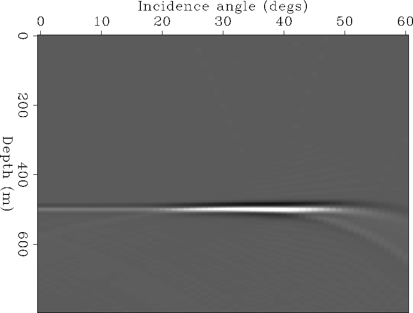 |
|
pws-img
Figure 10 Angle-dependent reflectivity image obtained by the plane wave synthesis imaging. | 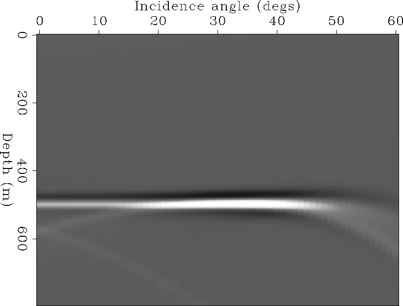 |
|
ava
Figure 11 Angle-dependent reflection coefficient as a function of the angle of incidence: (a) the theoretical result, (b) the result of profile imaging with conventional imaging condition, (c) the result of profile imaging with de Bruin's imaging condition, and (d) the result of plane wave synthesis imaging. | 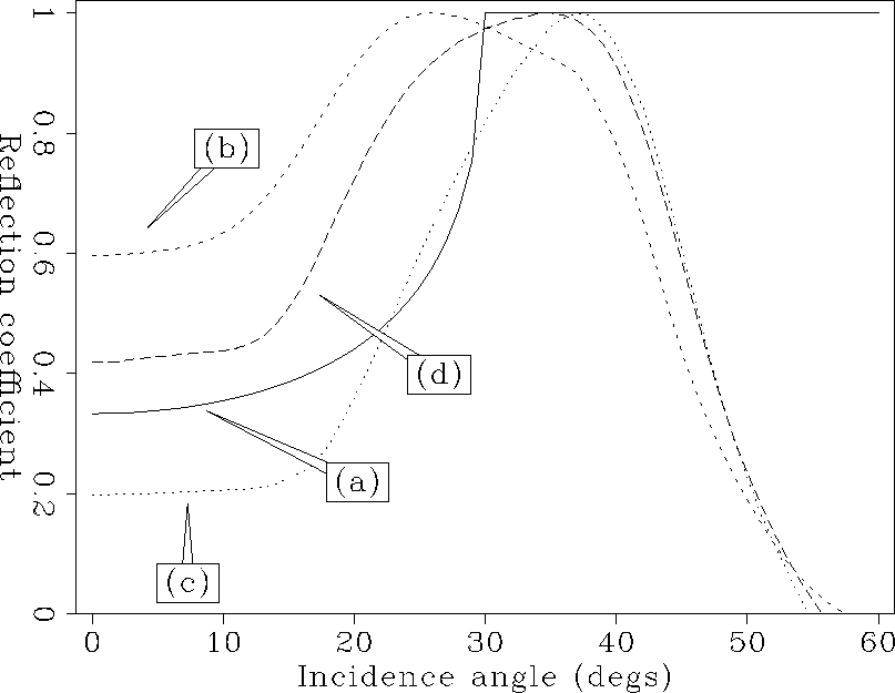 |
 |
|
marm-ava-rfl-com-1
Figure 13 Angle-dependent reflectivity obtained by PWS imaging (left) and theoretical reflectivity (right) for location (a). |  |
|
marm-ava-rfl-com-2
Figure 14 Angle-dependent reflectivity obtained by PWS imaging (left) and theoretical reflectivity (right) for location (b). |  |
|
marm-ava-rfl-com-3
Figure 15 Angle-dependent reflectivity obtained by PWS imaging (left) and theoretical reflectivity (right) for location (c). | 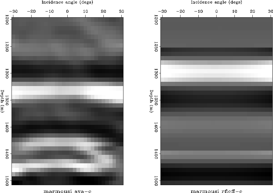 |
|
marm-ava-rfl-com-4
Figure 16 Angle-dependent reflectivity obtained by PWS imaging (left) and theoretical reflectivity (right) for location (d). | 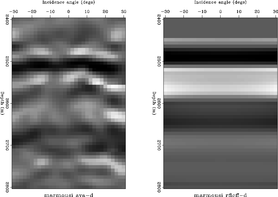 |