Next: Imaging conditions
Up: Angle-dependent reflectivity recovery
Previous: Reflectivity matrix
In prestack imaging, the first step is
the extrapolation of the source and received wave fields into subsurface.
The source and received wave fields are extrapolated
recursively for each depth level as follows:
|  |
(46) |
and
|  |
(47) |
where  denotes the adjoint and implies
that the received wave field is extrapolated backward in time.
By substituting equations (
denotes the adjoint and implies
that the received wave field is extrapolated backward in time.
By substituting equations (![[*]](http://sepwww.stanford.edu/latex2html/cross_ref_motif.gif) ) and () into
the forward model (equation ()), we have
) and () into
the forward model (equation ()), we have
|  |
(48) |
If we assume that the extrapolation operator W is a unitary operator,
equation () becomes
|  |
(49) |
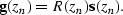
Then using the above relation, we perform the imaging
to retrieve reflectivity matrix R(zn)
from  and
and  for each depth level.
Therefore, one of the most important properties
of the extrapolation operator is the unitary
that makes equation () valid.
Even though many algorithms based on the wave equation
are accepted as unitary operators,
each algorithm has a different property
in terms of closeness to unitary.
Among the many extrapolation algorithms which allows
lateral velocity changes like finite-difference Claerbout (1985),
PSPI Gazdag and Sguazzero (1984) and split-step Fourier Stoffa and Fokkema (1990).
I chose the split-step Fourier method Stoffa and Fokkema (1990)
for this thesis because of its pseudounitary property (Appendix A).
To show the closeness to unitary of the split-step Fourier
extrapolation, I tested a plane wave extrapolation followed by
its adjoint operator in the Marmousi velocity model.
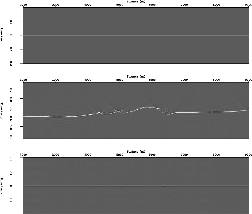
The input is a plane wave which is horizontally aligned spikes
at time equals zero (Figure (a)).
Figure (b) shows synthesis operator obtained by
extrapolating a plane wave from depth level 800 m to surface.
Figure (c) shows source wave field obtained by
applying its adjoint operator to the synthesis operator
which is extrapolating the synthesis operator
at surface to depth level 800 m.
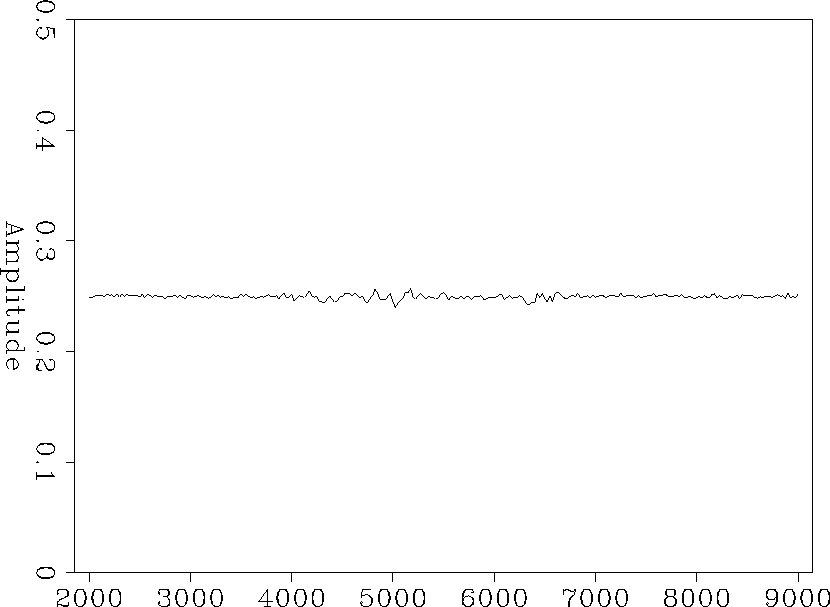
Figure is amplitude of the source wave field
(Figure (c)) along the plane wave.
unitary
Figure 3 Unitary property of the Split-step Fourier method.
Top : Input plane wave ( . Middle : Synthesis operator  . Bottom : source wave field at the datum
  .
.


 unitary-amp
Figure 4 Amplitude of source wave field at datum level.
Next: Imaging conditions
Up: Angle-dependent reflectivity recovery
Previous: Reflectivity matrix
Stanford Exploration Project
2/5/2001