

Next: From to
Up: Measuring
Previous: Event picking
The computation of traveltime errors along the reflectors picked in
the poststack image requires RMO velocity analysis.
Measuring RMO implies relative movement of
the reflection events in the common reflection point (CRP) gathers
according to the different travel paths that each event follows.
Conventionally, RMO velocity analysis is
performed in the common surface location (CSL) gather
after prestack migration.
The RMO velocity obtained from the CSL gather after
prestack migration does not reflect the correct
residual movement of CRP images
because CRP images are not located in
a CSL gather when a reflector has a dip.
Therefore, we need to apply residual dip moveout (RDMO)
before RMO velocity analysis of CSL gathers Etgen (1990)
or else apply a dip-dependent RMO velocity analysis
that is very difficult to implement or is not practical
Zhang (1990).
Even though surface-oriented planewave synthesis imaging
also shows residual moveout in CSL gathers,
it is not easy to quantify in terms of residual velocity.
This is because of the lack of the information about the
implied ray trajectories.
Since both the source and the received wave field
used in planewave synthesis imaging are plane waves,
we do not know which source and receiver locations
correspond to an image.
Therefore, we are forced to update the model
qualitatively using the curvature of the RMO curves
Whitmore and Garing (1993).
This drawback can be overcome by using reflector-oriented
planewave synthesis imaging.
With this method, the local incidence angle
on top of the reflector is predefined.
Thus, the image obtained can be interpreted as a wave field
that follows the ray trajectory extended
from the local incidence angle to the surface (Figure ![[*]](http://sepwww.stanford.edu/latex2html/cross_ref_motif.gif) ).
).
ray-extend
Figure 6 Ray trajectory extended using the local incidence angel on top of a reflection point.

For example, I applied reflector-dependent
planewave synthesis imaging for each reflector picked
in the previous section (Figure ![[*]](http://sepwww.stanford.edu/latex2html/cross_ref_motif.gif) ).
Figures
).
Figures ![[*]](http://sepwww.stanford.edu/latex2html/cross_ref_motif.gif) through
through ![[*]](http://sepwww.stanford.edu/latex2html/cross_ref_motif.gif) show
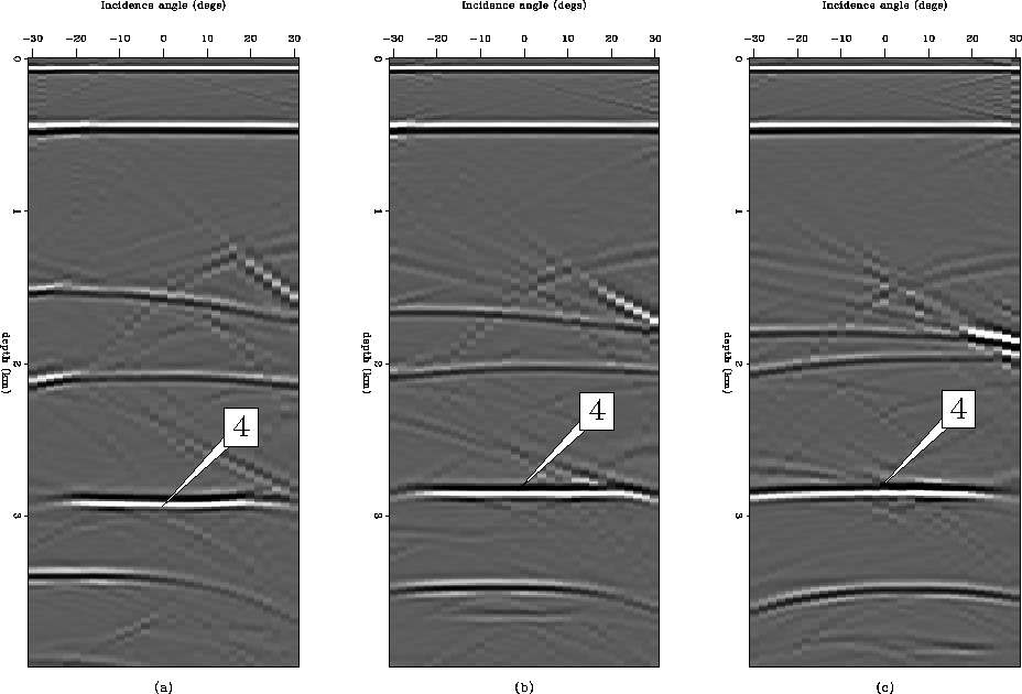
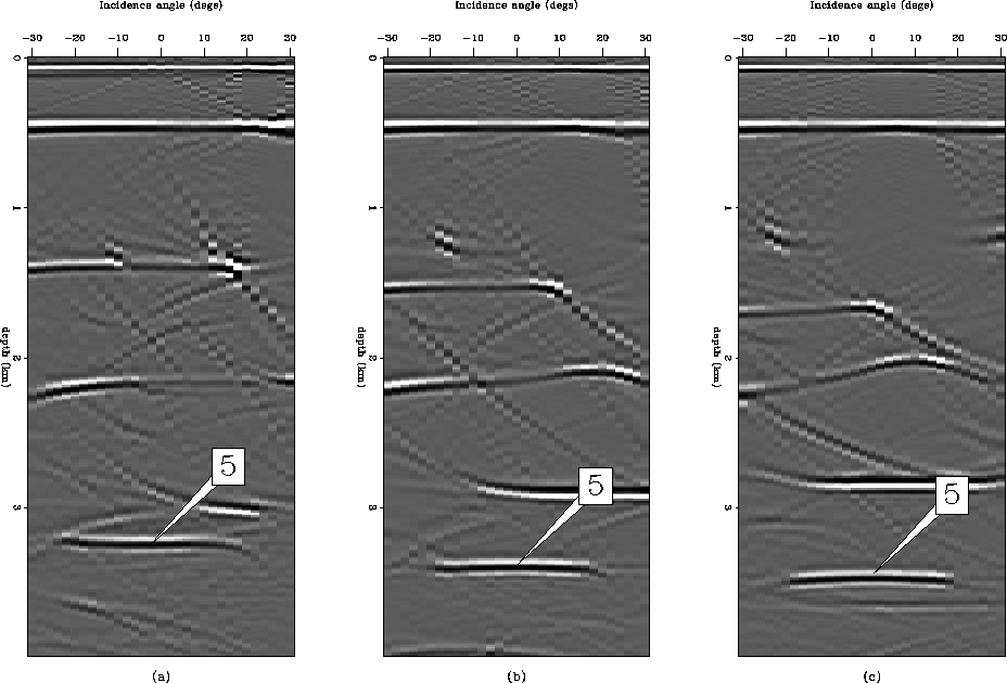
some of the resulting CSL gathers.
In contrast to the CSL gathers
obtained from surface-oriented PWS imaging,
each reflector image in the corresponding
reflector-oriented PWS imaging shows a symmetric RMO pattern
with respect to the normal incidence angle.
The reason of the symmetric RMO pattern
is that a ray that follows the shortest path from reflector
to surface would have normal incidence angle to the reflector.
show
some of the resulting CSL gathers.
In contrast to the CSL gathers
obtained from surface-oriented PWS imaging,
each reflector image in the corresponding
reflector-oriented PWS imaging shows a symmetric RMO pattern
with respect to the normal incidence angle.
The reason of the symmetric RMO pattern
is that a ray that follows the shortest path from reflector
to surface would have normal incidence angle to the reflector.
To quantify the residual moveout shown
in the reflector-oriented PWS imaging,
we can use the accurate dip-dependent RMO equation
derived by Zhang 1990.
However, the residual moveout equation is derived
under the assumption that the medium above the reflector
has constant velocity and the ray trajectories are straight lines,
which is not true when we are dealing with a variable-velocity medium.
Therefore, for the convenience of velocity analysis,
I derived a simplified RMO equation for a dipping event
that resembles the RMO equation for a flat reflector.
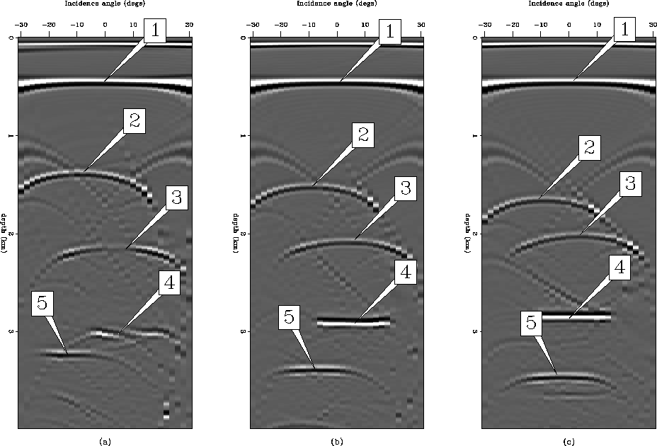
crp-iter0
Figure 7 Three CSL gathers at (a) 3 km, (b) 3.5 km, and (c) 4 km
from the prestack image cube that was obtained by
synthesizing plane waves at the surface.


 crp-iter0-2
Figure 8 Three CSL gathers at (a) 3 km, (b) 3.5 km, and (c) 4 km
from the prestack image cube that was obtained by
synthesizing plane waves at reflector number 2.


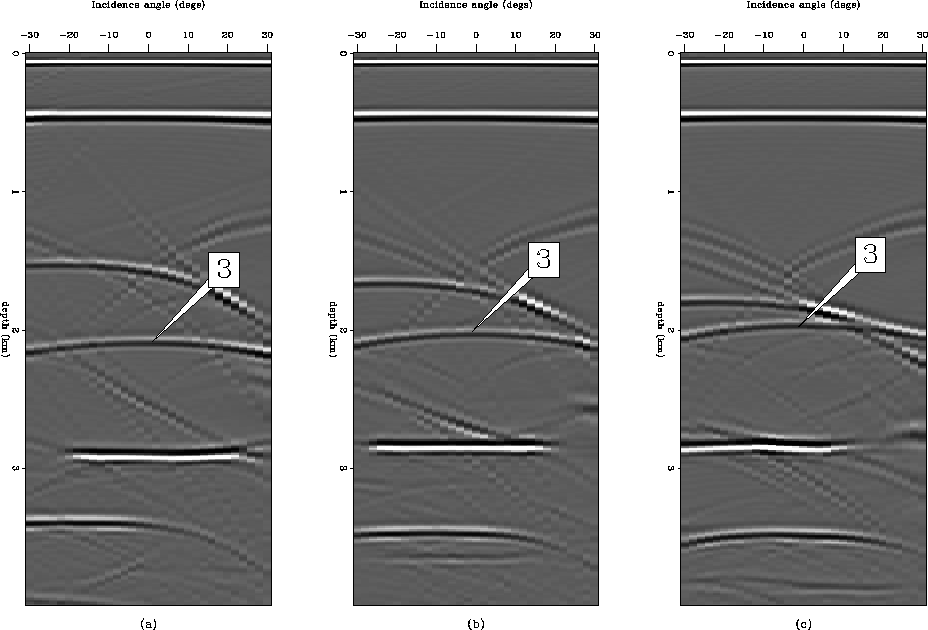
 crp-iter0-3
Figure 9 Three CSL gathers at (a) 3 km, (b) 3.5 km, and (c) 4 km
from the prestack image cube that was obtained by
synthesizing plane waves at reflector number 3.


 crp-iter0-4
Figure 10 Three CSL gathers at (a) 3 km, (b) 3.5 km, and (c) 4 km
from the prestack image cube that was obtained by
synthesizing plane waves at reflector number 4.


 crp-iter0-5
Figure 11 Three CSL gathers at (a) 3 km, (b) 3.5 km, and (c) 4 km
from the prestack image cube that was obtained by
synthesizing plane waves at reflector number 5.


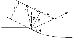
Let us consider a dipping reflector as shown in Figure ![[*]](http://sepwww.stanford.edu/latex2html/cross_ref_motif.gif) .
The depth to a reflection point is z,
the average slowness of the medium to the reflector is
.
The depth to a reflection point is z,
the average slowness of the medium to the reflector is  ,and t is the recorded traveltime.
If a planewave source has the incidence angle
  to the reflector,
the ray path from and to the reflector will be a straight line,
and the presummed half offset h of the ray path
can be approximately calculated
from the incidence angle
  of the planewave,
the reflector depth z, and the dip of the reflector
  , as follows :
|  |
(27) |
where  and represents the normal distance
from reflector to the surface.
If we assume n=m (see Figure ![[*]](http://sepwww.stanford.edu/latex2html/cross_ref_motif.gif) ),
the traveltime is given by
),
the traveltime is given by
|  |
(28) |
After migration with the slowness of the medium,
the image under a surface location will be at the same depth z.
If we migrate with an average slowness  instead of the slowness of the medium itself,
the image under a surface location will be at depth zm.
In this case, the traveltime is given by
|  |
(29) |
where  .
crp-ray
Figure 12 For a reflector of dipping angle  , a plane wave satisfies
Snell's law.

Note that the traveltime, t,
is the same in equations (![[*]](http://sepwww.stanford.edu/latex2html/cross_ref_motif.gif) ) and (
) and (![[*]](http://sepwww.stanford.edu/latex2html/cross_ref_motif.gif) )
because it is an observed quantity.
Eliminating t from equations (
)
because it is an observed quantity.
Eliminating t from equations (![[*]](http://sepwww.stanford.edu/latex2html/cross_ref_motif.gif) ) and (
) and (![[*]](http://sepwww.stanford.edu/latex2html/cross_ref_motif.gif) ),
we obtain
),
we obtain
|  |
(30) |
where
|  |
(31) |
Equation (![[*]](http://sepwww.stanford.edu/latex2html/cross_ref_motif.gif) ) gives a relation
between the apparent depth, zm, and the actual depth, z.
They are linked through the parameter
) gives a relation
between the apparent depth, zm, and the actual depth, z.
They are linked through the parameter  .Note that they are equal regardless of the offset or
incidence angle of the planewave
when the slowness used in migration is equal to
the slowness of the medium (
 ).
This is the essence of the velocity analysis principle in the CSL gather;
the image in a CLS gather is aligned
horizontally if the velocity model is correct.
When
  is not equal to 1,
there is both a moveout as a function of offset
and a shift at zero offset.
At each depth point along the reflector,
RMO is defined by the parameter  in equation (
![[*]](http://sepwww.stanford.edu/latex2html/cross_ref_motif.gif) ).
The data is then summed along this curved trajectory.
The summation is done for a range of
).
The data is then summed along this curved trajectory.
The summation is done for a range of  ,and the sum is largest for the value of
  that matches the curvature.
Because some signals may be weaker than others,
the sum is normalized.
This normalized summation is similar
to the normalized summation along a hyperbola using the NMO equation,
commonly known as semblance Taner and Koehler (1969).
If the data in a CSL gather is
  ,then searching for curvature produces
the semblance panel
  , defined as
| ![\begin{displaymath}
g(z_m,\gamma) = {[ \sum_\alpha p( z=\sqrt{z_m^2 + (\gamma^2-...
...qrt{z_m^2 + (\gamma^2-1)h(\alpha)^2 \cos^2\theta },\alpha)]^2}.\end{displaymath}](img71.gif) |
(32) |
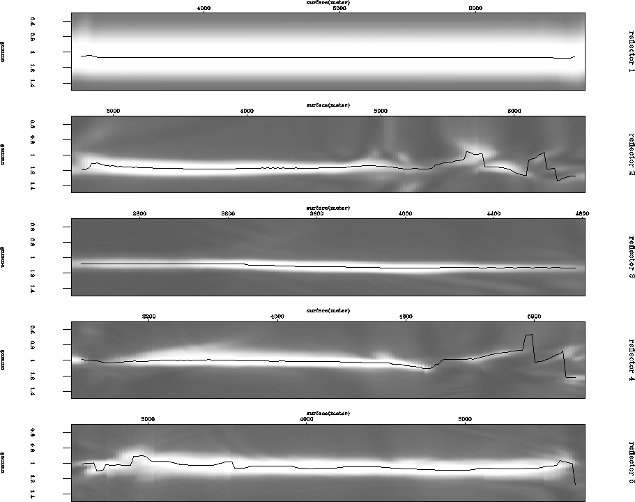
Figure ![[*]](http://sepwww.stanford.edu/latex2html/cross_ref_motif.gif) shows that the semblance velocity analysis panel
for the reflectors picked with
shows that the semblance velocity analysis panel
for the reflectors picked with  values, which are the maximum
semblance values for each CSL gather, are on top of semblance panel.
As Figure
 ![[*]](http://sepwww.stanford.edu/latex2html/cross_ref_motif.gif) shows,
some portions of the reflectors have much lower semblance values
than other portions.
shows,
some portions of the reflectors have much lower semblance values
than other portions.
In order to avoid possible bias in inversion
from this erroneous information,
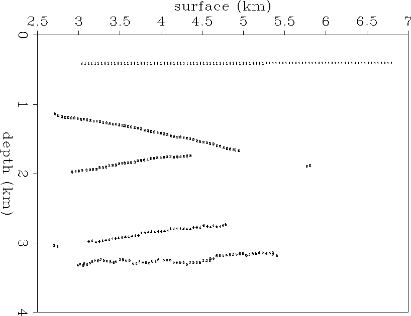
I excluded reflection locations that have semblance values below 0.4.
The rest of the reflectors to be used in the inversion
are shown in Figure ![[*]](http://sepwww.stanford.edu/latex2html/cross_ref_motif.gif) .
.
velan-iter0
Figure 13 Semblance stack panels for the picked reflectors. The  values that
correspond to the maximum semblance value are overlaid
on top the semblance panel with lines.


 npick0
Figure 14 The portions of the picked reflectors to be used for determining
traveltime error. The reflector locations that have below .4
in semblance value were excluded in traveltime error calculation.


Next: From to
Up: Measuring
Previous: Event picking
Stanford Exploration Project
2/5/2001
![[*]](http://sepwww.stanford.edu/latex2html/cross_ref_motif.gif) ).
).
![[*]](http://sepwww.stanford.edu/latex2html/cross_ref_motif.gif) ).
).

![[*]](http://sepwww.stanford.edu/latex2html/cross_ref_motif.gif) ).
Figures
).
Figures ![[*]](http://sepwww.stanford.edu/latex2html/cross_ref_motif.gif) through
through ![[*]](http://sepwww.stanford.edu/latex2html/cross_ref_motif.gif) show
some of the resulting CSL gathers.
In contrast to the CSL gathers
obtained from surface-oriented PWS imaging,
each reflector image in the corresponding
reflector-oriented PWS imaging shows a symmetric RMO pattern
with respect to the normal incidence angle.
The reason of the symmetric RMO pattern
is that a ray that follows the shortest path from reflector
to surface would have normal incidence angle to the reflector.
show
some of the resulting CSL gathers.
In contrast to the CSL gathers
obtained from surface-oriented PWS imaging,
each reflector image in the corresponding
reflector-oriented PWS imaging shows a symmetric RMO pattern
with respect to the normal incidence angle.
The reason of the symmetric RMO pattern
is that a ray that follows the shortest path from reflector
to surface would have normal incidence angle to the reflector.

![[*]](http://sepwww.stanford.edu/latex2html/cross_ref_motif.gif) .
The depth to a reflection point is z,
the average slowness of the medium to the reflector is
.
The depth to a reflection point is z,
the average slowness of the medium to the reflector is ![]() ,and t is the recorded traveltime.
If a planewave source has the incidence angle
,and t is the recorded traveltime.
If a planewave source has the incidence angle ![]() to the reflector,
the ray path from and to the reflector will be a straight line,
and the presummed half offset h of the ray path
can be approximately calculated
from the incidence angle
to the reflector,
the ray path from and to the reflector will be a straight line,
and the presummed half offset h of the ray path
can be approximately calculated
from the incidence angle ![]() of the planewave,
the reflector depth z, and the dip of the reflector
of the planewave,
the reflector depth z, and the dip of the reflector ![]() , as follows :
, as follows :
![[*]](http://sepwww.stanford.edu/latex2html/cross_ref_motif.gif) ),
the traveltime is given by
),
the traveltime is given by
![[*]](http://sepwww.stanford.edu/latex2html/cross_ref_motif.gif) ) and (
) and (![[*]](http://sepwww.stanford.edu/latex2html/cross_ref_motif.gif) )
because it is an observed quantity.
Eliminating t from equations (
)
because it is an observed quantity.
Eliminating t from equations (![[*]](http://sepwww.stanford.edu/latex2html/cross_ref_motif.gif) ) and (
) and (![[*]](http://sepwww.stanford.edu/latex2html/cross_ref_motif.gif) ),
we obtain
),
we obtain
![[*]](http://sepwww.stanford.edu/latex2html/cross_ref_motif.gif) ) gives a relation
between the apparent depth, zm, and the actual depth, z.
They are linked through the parameter
) gives a relation
between the apparent depth, zm, and the actual depth, z.
They are linked through the parameter ![]() .Note that they are equal regardless of the offset or
incidence angle of the planewave
when the slowness used in migration is equal to
the slowness of the medium (
.Note that they are equal regardless of the offset or
incidence angle of the planewave
when the slowness used in migration is equal to
the slowness of the medium (![]() ).
This is the essence of the velocity analysis principle in the CSL gather;
the image in a CLS gather is aligned
horizontally if the velocity model is correct.
When
).
This is the essence of the velocity analysis principle in the CSL gather;
the image in a CLS gather is aligned
horizontally if the velocity model is correct.
When ![]() is not equal to 1,
there is both a moveout as a function of offset
and a shift at zero offset.
is not equal to 1,
there is both a moveout as a function of offset
and a shift at zero offset.
![]() in equation (
in equation (![[*]](http://sepwww.stanford.edu/latex2html/cross_ref_motif.gif) ).
The data is then summed along this curved trajectory.
The summation is done for a range of
).
The data is then summed along this curved trajectory.
The summation is done for a range of ![]() ,and the sum is largest for the value of
,and the sum is largest for the value of ![]() that matches the curvature.
Because some signals may be weaker than others,
the sum is normalized.
This normalized summation is similar
to the normalized summation along a hyperbola using the NMO equation,
commonly known as semblance Taner and Koehler (1969).
If the data in a CSL gather is
that matches the curvature.
Because some signals may be weaker than others,
the sum is normalized.
This normalized summation is similar
to the normalized summation along a hyperbola using the NMO equation,
commonly known as semblance Taner and Koehler (1969).
If the data in a CSL gather is ![]() ,then searching for curvature produces
the semblance panel
,then searching for curvature produces
the semblance panel ![]() , defined as
, defined as
![[*]](http://sepwww.stanford.edu/latex2html/cross_ref_motif.gif) shows that the semblance velocity analysis panel
for the reflectors picked with
shows that the semblance velocity analysis panel
for the reflectors picked with ![]() values, which are the maximum
semblance values for each CSL gather, are on top of semblance panel.
As Figure
values, which are the maximum
semblance values for each CSL gather, are on top of semblance panel.
As Figure ![[*]](http://sepwww.stanford.edu/latex2html/cross_ref_motif.gif) shows,
some portions of the reflectors have much lower semblance values
than other portions.
shows,
some portions of the reflectors have much lower semblance values
than other portions.
![[*]](http://sepwww.stanford.edu/latex2html/cross_ref_motif.gif) .
.
