![[*]](http://sepwww.stanford.edu/latex2html/cross_ref_motif.gif) ).
With this acquisition, every receiver will record reflected wave fields
caused by every source wave field.
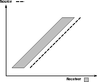
In practice, however, a moving one-side spread
(Figure
).
With this acquisition, every receiver will record reflected wave fields
caused by every source wave field.
In practice, however, a moving one-side spread
(Figure ![[*]](http://sepwww.stanford.edu/latex2html/cross_ref_motif.gif) ) is the typical acquisition pattern
in marine surveys.
) is the typical acquisition pattern
in marine surveys.
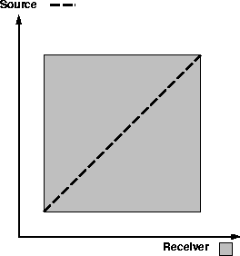
The ideal acquisition pattern for plane-wave synthesis
is a fixed-split spread with wide aperture (Figure ![[*]](http://sepwww.stanford.edu/latex2html/cross_ref_motif.gif) ).
With this acquisition, every receiver will record reflected wave fields
caused by every source wave field.
In practice, however, a moving one-side spread
(Figure
).
With this acquisition, every receiver will record reflected wave fields
caused by every source wave field.
In practice, however, a moving one-side spread
(Figure ![[*]](http://sepwww.stanford.edu/latex2html/cross_ref_motif.gif) ) is the typical acquisition pattern
in marine surveys.
) is the typical acquisition pattern
in marine surveys.
The forward model in equation (![[*]](http://sepwww.stanford.edu/latex2html/cross_ref_motif.gif) )
implicitly assumes an infinite aperture experiment.
In order to model correctly,
we need to incorporate the aperture effect as follows:
)
implicitly assumes an infinite aperture experiment.
In order to model correctly,
we need to incorporate the aperture effect as follows:
| (19) |
![[*]](http://sepwww.stanford.edu/latex2html/cross_ref_motif.gif) )
is no longer valid.
In order to overcome this problem, we need to fill the missing traces
before wave stacking.
)
is no longer valid.
In order to overcome this problem, we need to fill the missing traces
before wave stacking.
In the case of the one-sided spread acquisition, we can expand
the acquisition area using the principle of reciprocity,
which states that if we exchange the source and receiver positions,
we would record the same seismic trace at the source position.
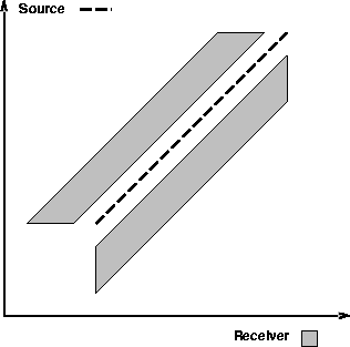
The acquisition pattern is expanded using the principle of reciprocity
as depicted in Figure ![[*]](http://sepwww.stanford.edu/latex2html/cross_ref_motif.gif) .
.
 |
 |
 |
However, Figure ![[*]](http://sepwww.stanford.edu/latex2html/cross_ref_motif.gif) shows
that we still have some missing regions
in near and far offset after the acquisition
expansion that uses the principle of reciprocity.
The missing part of the far-offset limits the angle coverage of
the reflectivity information.
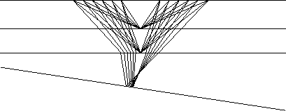
Since the maximum incidence angle of the source wave field
generally decreases as the depth of reflector increases
(Figure
shows
that we still have some missing regions
in near and far offset after the acquisition
expansion that uses the principle of reciprocity.
The missing part of the far-offset limits the angle coverage of
the reflectivity information.
Since the maximum incidence angle of the source wave field
generally decreases as the depth of reflector increases
(Figure ![[*]](http://sepwww.stanford.edu/latex2html/cross_ref_motif.gif) ), we can avoid the effects of cable length
by synthesizing different incidence angle ranges at every depth level.
), we can avoid the effects of cable length
by synthesizing different incidence angle ranges at every depth level.
The effects of the missing part of the near offset
are not as easily avoided as those of the missing part of the far offset,
because the effect of missing near-offset traces differ in terms of
missing reflection angle ranges from depth to depth and are located around
the normal incidence angle to reflectors (Figure ![[*]](http://sepwww.stanford.edu/latex2html/cross_ref_motif.gif) ).
In order to obtain a good image in every constant angle illumination,
we need to interpolate the missing near offset traces.
).
In order to obtain a good image in every constant angle illumination,
we need to interpolate the missing near offset traces.
 |