

Next: Image stacking versus patching
Up: Imaging by wavefront synthesis
Previous: Controlling incidence angle
After the wavefront synthesis,
the synthesized stack is expressed as
equation (![[*]](http://sepwww.stanford.edu/latex2html/cross_ref_motif.gif) ),
and if we write it with a full operator, it becomes
),
and if we write it with a full operator, it becomes
|  |
(14) |
We can notice that this equation has the same form as the forward
model of a shot record (equation (![[*]](http://sepwww.stanford.edu/latex2html/cross_ref_motif.gif) )).
Therefore, the imaging is performed
in the same manner as profile imaging Claerbout (1985),
with
)).
Therefore, the imaging is performed
in the same manner as profile imaging Claerbout (1985),
with  as the upcoming wave and
 as the downgoing wave.
According to the profile imaging concept, the reflectors exist
in the earth at places where the downgoing wave
is time-coincident with an upcoming wave Claerbout (1985).
It can be explained by two procedures: extrapolation and imaging.
By recalling that the extrapolation operator is unitary,
after extrapolating the upcoming and downgoing wavefield
recursively, we have
|  |
(15) |
where  denotes the adjoint.
For each depth level, extrapolation is performed as follows:
|  |
(16) |
and
|  |
(17) |
The upcoming waves are extrapolated backward in time,
the downgoing waves, forward in time.
Keeping in mind that the upcoming wavefield is the convolution
of the reflectivity with the downgoing wave field,
we can obtain the reflection coefficient
from equations (![[*]](http://sepwww.stanford.edu/latex2html/cross_ref_motif.gif) ) and (
) and (![[*]](http://sepwww.stanford.edu/latex2html/cross_ref_motif.gif) )
by deconvolving
)
by deconvolving  from
from
 as follows:
|  |
(18) |
In equation (![[*]](http://sepwww.stanford.edu/latex2html/cross_ref_motif.gif) ),
),
 represents a small positive value
that is introduced for stability
because
  may contain zeros,
and the summation of all frequency components
is equivalent to inverse Fourier transforming and
takes the zero-time component.
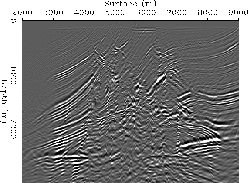
pws-mar-pln-0
Figure 17 Image obtained by synthesizing a plane-wave with p = 0 (s/m) at surface.


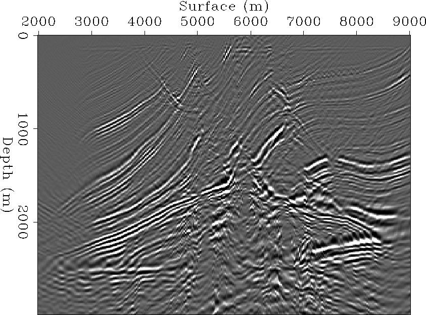
 pws-mar-pos-0
Figure 18 Image obtained by synthesizing a plane-wave with p = .0001 (s/m) at surface.


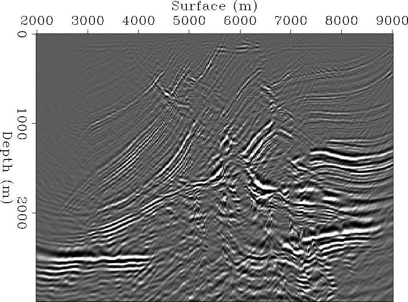
 pws-mar-pln-1
Figure 19 Image obtained by synthesizing a plane-wave with p = 0 (s/m) at 1200 m depth.


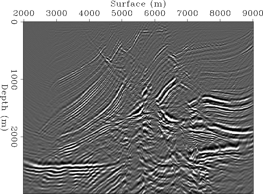
 pws-mar-pos-1
Figure 20 Image obtained by synthesizing a plane-wave with p = .0001 (s/m) at 1200 m depth.


 pws-mar-pos-2
Figure 21 Image obtained by synthesizing a plane-wave with 10 degrees angle at 1200 m depth.


Next: Image stacking versus patching
Up: Imaging by wavefront synthesis
Previous: Controlling incidence angle
Stanford Exploration Project
2/5/2001
![[*]](http://sepwww.stanford.edu/latex2html/cross_ref_motif.gif) ),
and if we write it with a full operator, it becomes
),
and if we write it with a full operator, it becomes
![[*]](http://sepwww.stanford.edu/latex2html/cross_ref_motif.gif) ),
and if we write it with a full operator, it becomes
),
and if we write it with a full operator, it becomes
![[*]](http://sepwww.stanford.edu/latex2html/cross_ref_motif.gif) )).
Therefore, the imaging is performed
in the same manner as profile imaging Claerbout (1985),
with
)).
Therefore, the imaging is performed
in the same manner as profile imaging Claerbout (1985),
with ![[*]](http://sepwww.stanford.edu/latex2html/cross_ref_motif.gif) ) and (
) and (![[*]](http://sepwww.stanford.edu/latex2html/cross_ref_motif.gif) )
by deconvolving
)
by deconvolving ![]() from
from
![]() as follows:
as follows:
![[*]](http://sepwww.stanford.edu/latex2html/cross_ref_motif.gif) ),
),


