

Next: Imaging the synthesized stack
Up: Wavefront synthesis using wave
Previous: Wavefront synthesis along an
In the previous sections the slanted wavefront was
synthesized by using the ray parameter p.
If the reflector in the subsurface is generally gentle and
the lateral velocity change is small,
the slanted wavefronts with constant ray parameters
are enough to retrieve the angle-dependent reflectivity.
However, if the reflector in the subsurface
has a complex structure or the lateral velocity change is not small,
a slanted wavefront with a constant ray parameter
is not enough to retrieve the angle-dependent reflectivity
because one need to calculate the incidence angle using the velocity
of the subsurface location, which corresponds to the ray parameter
of the subsurface location.
We then need a plane-wave with a constant-incidence angle
to reflectors instead.
In order to synthesize an areal shot record
for a slanted wavefront with a constant-incidence angle at a depth level,
the impulse in each trace of the predefined wavefield,
 , must have time lag,
  ,with respect to every other trace.
If the trace interval is
|  |
(11) |
where vh is the horizontal phase velocity of the propagating
wavefront at depth level zn.
Snell's law states that for a stratified earth
|  |
(12) |
where p is the ray parameter,
and v(z) is the depth-dependent velocity of the
medium.
Combining equations (![[*]](http://sepwww.stanford.edu/latex2html/cross_ref_motif.gif) ) and (
) and (![[*]](http://sepwww.stanford.edu/latex2html/cross_ref_motif.gif) ),
we can obtain the time lag,
),
we can obtain the time lag,  , between the traces
to simulate a plane-wave which has a constant incidence angle
to the depth level as shown below:
|  |
(13) |
Now the synthesized wavefront becomes
![\begin{displaymath}
\bar s_j(z_n) = \exp [i\omega \tau_j]\end{displaymath}](img21.gif)
with

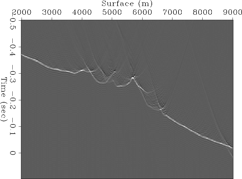
marm-syn-pos-2
Figure 14 Synthesis operator that synthesizes a plane-wave with 10 degrees angle at 1200 m depth.


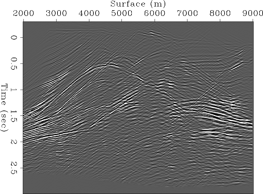
 marm-stk-pos-2
Figure 15 Wave-stacked section of Marmousi data set with synthesis operator shown in Figure ![[*]](http://sepwww.stanford.edu/latex2html/cross_ref_motif.gif) .
.


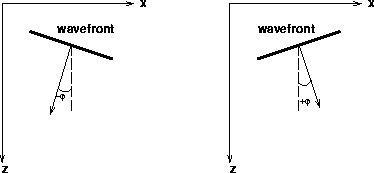
The sign convention of the angle,  , for the slanted wavefront
used in this thesis is shown in Figure
 ![[*]](http://sepwww.stanford.edu/latex2html/cross_ref_motif.gif) .
Figure
.
Figure ![[*]](http://sepwww.stanford.edu/latex2html/cross_ref_motif.gif) is the stacked section obtained by synthesizing
a plane wave with 10 degrees of incidence angle at 1200 m depth
(Figure
is the stacked section obtained by synthesizing
a plane wave with 10 degrees of incidence angle at 1200 m depth
(Figure ![[*]](http://sepwww.stanford.edu/latex2html/cross_ref_motif.gif) ).
It looks very similar to the synthesized stack with a constant ray parameter
(Figure
).
It looks very similar to the synthesized stack with a constant ray parameter
(Figure ![[*]](http://sepwww.stanford.edu/latex2html/cross_ref_motif.gif) ) at the same depth level, but
the difference between them becomes clear in the images shown
in Figures
) at the same depth level, but
the difference between them becomes clear in the images shown
in Figures ![[*]](http://sepwww.stanford.edu/latex2html/cross_ref_motif.gif) and
and ![[*]](http://sepwww.stanford.edu/latex2html/cross_ref_motif.gif) .
The image obtained by synthesizing a constant incidence angle
is readily interpretable in terms of an angle-dependent reflectivity
of the reflectors where the plane-wave is synthesized,
since we can easily calculate the incidence angle
to reflector from the angle of synthesized plane-wave and the dip of reflector.
.
The image obtained by synthesizing a constant incidence angle
is readily interpretable in terms of an angle-dependent reflectivity
of the reflectors where the plane-wave is synthesized,
since we can easily calculate the incidence angle
to reflector from the angle of synthesized plane-wave and the dip of reflector.
anglesign
Figure 16 The sign convention used in this thesis for the slanted plane wavefront.


Next: Imaging the synthesized stack
Up: Wavefront synthesis using wave
Previous: Wavefront synthesis along an
Stanford Exploration Project
2/5/2001
![]() , must have time lag,
, must have time lag, ![]() ,with respect to every other trace.
If the trace interval is
,with respect to every other trace.
If the trace interval is ![]()
![[*]](http://sepwww.stanford.edu/latex2html/cross_ref_motif.gif) ) and (
) and (![[*]](http://sepwww.stanford.edu/latex2html/cross_ref_motif.gif) ),
we can obtain the time lag,
),
we can obtain the time lag, ![]()
![]()


![[*]](http://sepwww.stanford.edu/latex2html/cross_ref_motif.gif) .
.
![]() , for the slanted wavefront
used in this thesis is shown in Figure
, for the slanted wavefront
used in this thesis is shown in Figure ![[*]](http://sepwww.stanford.edu/latex2html/cross_ref_motif.gif) .
Figure
.
Figure ![[*]](http://sepwww.stanford.edu/latex2html/cross_ref_motif.gif) is the stacked section obtained by synthesizing
a plane wave with 10 degrees of incidence angle at 1200 m depth
(Figure
is the stacked section obtained by synthesizing
a plane wave with 10 degrees of incidence angle at 1200 m depth
(Figure ![[*]](http://sepwww.stanford.edu/latex2html/cross_ref_motif.gif) ).
It looks very similar to the synthesized stack with a constant ray parameter
(Figure
).
It looks very similar to the synthesized stack with a constant ray parameter
(Figure ![[*]](http://sepwww.stanford.edu/latex2html/cross_ref_motif.gif) ) at the same depth level, but
the difference between them becomes clear in the images shown
in Figures
) at the same depth level, but
the difference between them becomes clear in the images shown
in Figures ![[*]](http://sepwww.stanford.edu/latex2html/cross_ref_motif.gif) and
and ![[*]](http://sepwww.stanford.edu/latex2html/cross_ref_motif.gif) .
The image obtained by synthesizing a constant incidence angle
is readily interpretable in terms of an angle-dependent reflectivity
of the reflectors where the plane-wave is synthesized,
since we can easily calculate the incidence angle
to reflector from the angle of synthesized plane-wave and the dip of reflector.
.
The image obtained by synthesizing a constant incidence angle
is readily interpretable in terms of an angle-dependent reflectivity
of the reflectors where the plane-wave is synthesized,
since we can easily calculate the incidence angle
to reflector from the angle of synthesized plane-wave and the dip of reflector.
