

Next: FUTURE WORK
Up: Lumley: 4-D seismic steamflood
Previous: At 19 months
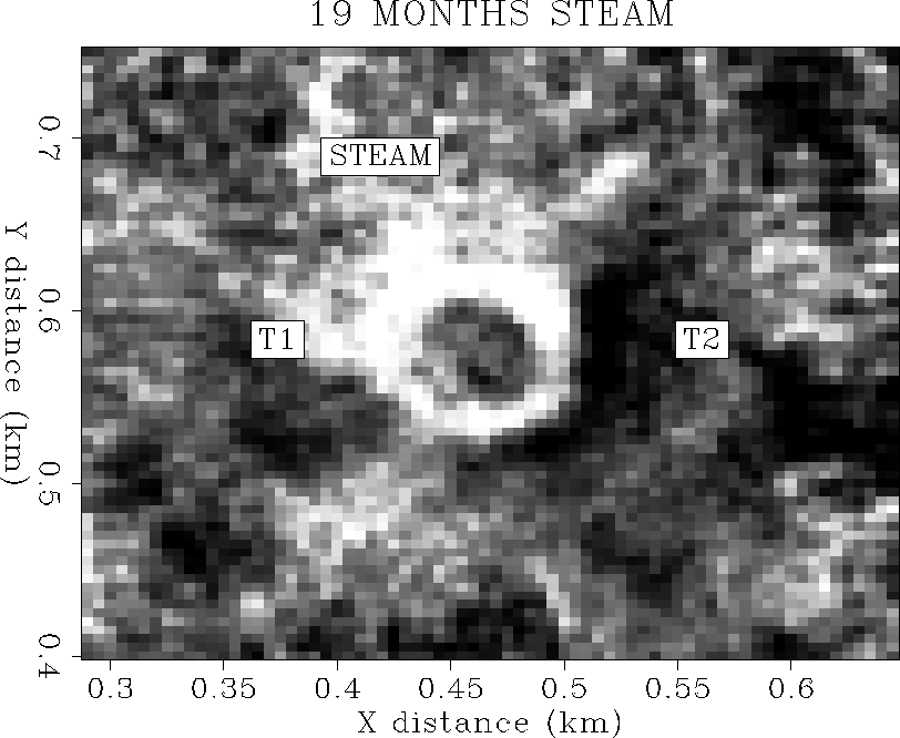
It appears that the bright reflection disk centered on the injector well
and the time delay beneath must indicate the extent of the steam zone, not
merely hot fluid. The rock physics analysis has shown that the steam
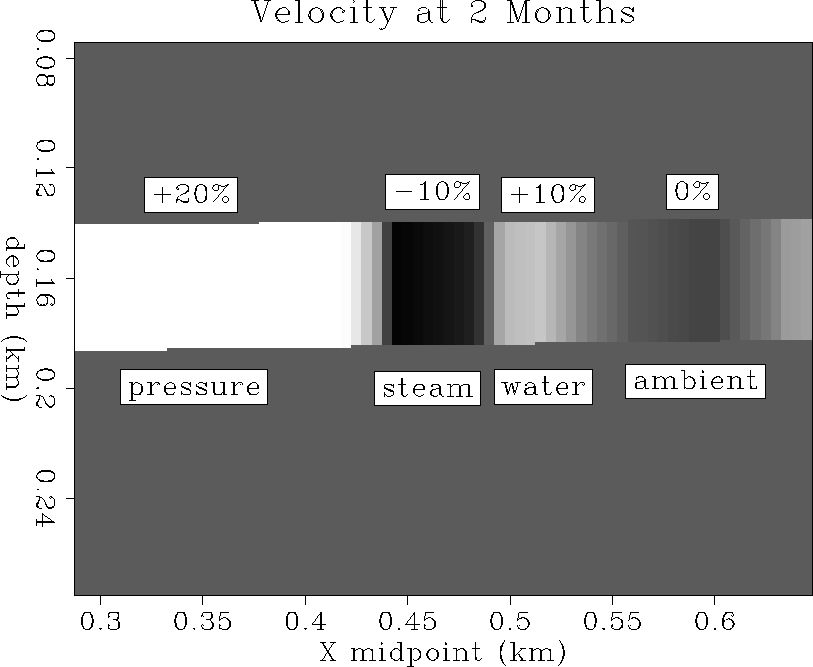
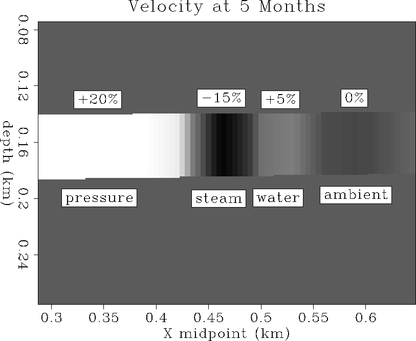
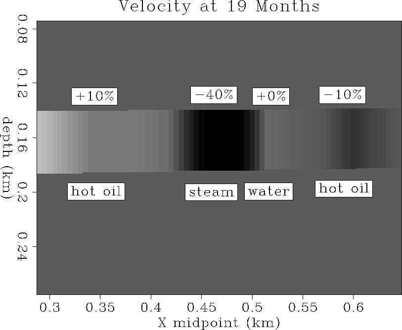
zone should be expected to show velocity decreases of up to 40%,
whereas hot water or oil increases velocity by only 10% or less.
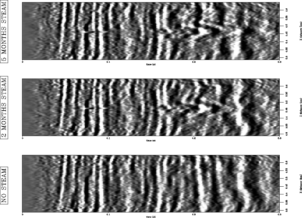
Finite difference modeling of a reasonable steamflood velocity model
shows strong diffractions and bright reflections emanating from the
steam zone, that can be interpreted to match similar features in the
field data. This analysis implies that the steam zone is about 40 m
in diameter at the top of the P reservoir, 80 m in diameter at the base
of the P reservoir, and heading to the north and west faster much
faster than the south and east. This correlates with
core measurements that the top part of the reservoir
is at least one order of magnitude less permeable than the bottom part,
and that for at least 13 months of steam injection, substantial heating had
arrived at the T1 temperature monitor well to the west, but not the T2
well to the east.
My analysis suggests that the hot oil ring may be seismically
transparent, but that the hot water ring might be visible since it
causes about a 10% velocity increase. Close inspection of the
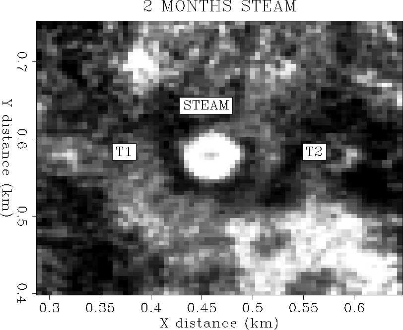
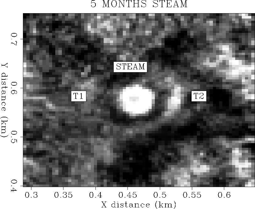
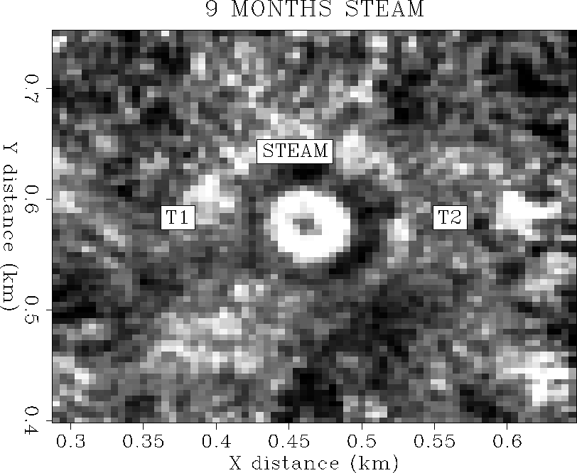
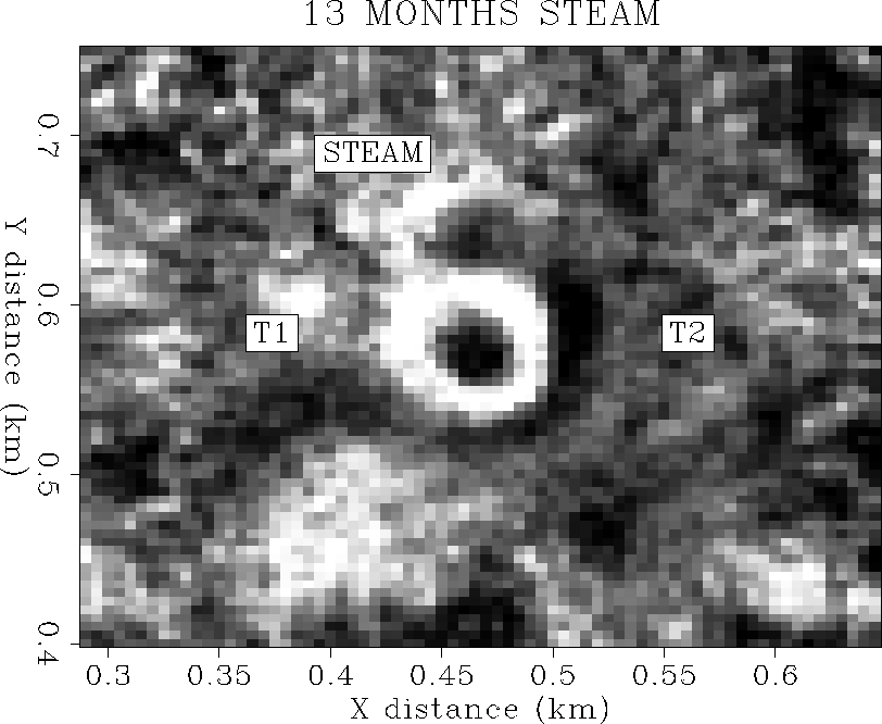
time slices in Figures 37 to 41
shows a thin dark gray ring surrounding the white steam disk.
This ring is about 15 m thick
and corresponds to time pull-up (velocity increase) in the migrated
profile sections. The dark gray
amplitude suggests it is of opposite reflection polarity to the steam zone,
which matches the predicted hot water properties.
This dark gray ring may be the seismic view of the hot water
steam condensate.
I have predicted that a large area of the 7-spot pattern
would be subject to a fast-propagating cold high-pressure front.
This pressure front should be seismically visible since it causes a
20% increase in velocity. Finite difference modeling shows that the
high-pressure front can cause time pull-ups on seismic events
due to velocity increase. The velocity models of Figures 30
to 34 show that the pressure front is propagating to the
west, but not the east. Correlating the pull-up to features in the time
slices of Figures 37 to 41 suggests
that the pressure front propagates both north and west, but not south or east.
Since the steam front is also observed to propagate to the northwest, but
not the southeast, after 1 year of steam injection, it appears that
mapping the early pressure front movement can be used to predict subsequent
thermal and steam front fluid-flow propagation directions,
many months in advance. This may be the most important result
of my analysis of the Duri 4-D seismic monitoring data set.
vres1-ann
Figure 30 Reservoir velocity at 2 months
 vres2-ann
Figure 31 Reservoir velocity at 5 months
 vres3-ann
Figure 32 Reservoir velocity at 9 months
 vres4-ann
Figure 33 Reservoir velocity at 13 months
 vres5-ann
Figure 34 Reservoir velocity at 19 months
 mig05a-ann
Figure 35 3-D migrated inlines from the first three 3-D surveys.
Baseline survey (left), first monitor after steam
injection (center), and second monitor survey (right).
 mig05b-ann
Figure 36 3-D migrated inlines from the last three 3-D surveys.
Third monitor survey after steam injection (left),
fourth monitor (center), and fifth monitor survey (right).
 m1-tslice-ann
Figure 37 3-D migrated time slice at the base
of the reservoir after 2 months of steam injection. T1 and T2 are the temperature observation well positions.
 m2-tslice-ann
Figure 38 3-D migrated time slice at the base
of the reservoir after 5 months of steam injection. T1 and T2 are the temperature observation well positions.
 m3-tslice-ann
Figure 39 3-D migrated time slice at the base
of the reservoir after 9 months of steam injection. T1 and T2 are the temperature observation well positions.
 m4-tslice-ann
Figure 40 3-D migrated time slice at the base
of the reservoir after 13 months of steam injection. T1 and T2 are the temperature observation well positions.
 m5-tslice-ann
Figure 41 3-D migrated time slice at the base
of the reservoir after 19 months of steam injection. T1 and T2 are the temperature observation well positions.
 temp
temp
Figure 42 Temperature observation well data to the west (T1) and
east (T2) of the steam injector.


Next: FUTURE WORK
Up: Lumley: 4-D seismic steamflood
Previous: At 19 months
Stanford Exploration Project
11/12/1997
