![[*]](http://sepwww.stanford.edu/latex2html/prev_gr.gif)
INTRODUCTION The DSR prestack migration equation, though defined for depth variable velocity, can be used to image media with strong velocity variations using a phase-shift plus interpolation (PSPI) or split-step correction. The split-step method is based on applying a phase-shift correction to the extrapolated wavefield, a correction that attempts to compensate for the lateral velocity variations. I show how to extend DSR prestack migration to lateral velocity media and exemplify the method by applying the new algorithm to the Marmousi dataset.
Split-step prestack migration The depth-variable-velocity prestack migration in offset-midpoint coordinates (Yilmaz, 1979) is formulated as
| |
(1) |
![]()
![\begin{displaymath}
{k_z(\omega,k_y,k_h)} \equiv
{ -{\rm sign}(\omega) \left[ \s...
...t{{\omega^2 \over v^2} -
{1 \over 4}(k_y-k_h)^2} \; \right] }.\end{displaymath}](img5.gif) |
(2) |
In parallel, the depth-variable-velocity zero-offset migration (Gazdag, 1978) is formulated as
| |
(3) |
 |
(4) |
For zero-offset migration, the idea of a
split-step correction appeared first
in Gazdag and Sguazzero's (1984) PSPI algorithm, but it
did not become a standalone technique until Stoffa et al. (1990)
reversed the order of the algorithm, permitting the correction
to be applied only once. The schematic flow of the two
algorithms is shown in Figure ![[*]](http://sepwww.stanford.edu/latex2html/cross_ref_motif.gif) , and the
split-step correction is represented by the box containing
the
, and the
split-step correction is represented by the box containing
the ![]() term.
term.
gazsplitheight=3.2in.The two Fourier
migration algorithms.
a) Phase Shift Plus Interpolation (PSPI).
b) Split-step Fourier Migration.
Gazdag and Sguazzero (1984) implement a technique in the
PSPI algorithm to ensure that all the zero dips (corresponding to the
case kx=0) are downward continued without distortion. The technique
consists of multiplying the wavefield ![]() with
the phase-shift correction factor
with
the phase-shift correction factor
![]()
![]()
![]()
![]()
![]()
The same result can be obtained via the Stoffa et al. (1990) algorithm, where the phase-correction term is contained in a single term, as follows:
![]()
For prestack migration, the two square roots in the phase term represent specifically the extrapolation term for the source and for the receiver. In other words if we downward extrapolate first the source, and second the receiver, we need in each case a different phase-correction term. The phase-correction term includes a laterally varying velocity function, vg(xg,z) for the geophone-field continuation and vs(xs,z) for the source-field continuation. A minor problem arises in the fact that the DSR prestack migration equation (1) is defined in midpoint and offset coordinates, while the velocity is defined in shot and geophone coordinates. We can easily go from one system to another using the transformation relations
 |
(5) |
The split-step correction term becomes
![]()
![]()
![[*]](http://sepwww.stanford.edu/latex2html/cross_ref_motif.gif) .
The last box represents the multiplication with the
split-step correction exponential term, where the slowness
difference
.
The last box represents the multiplication with the
split-step correction exponential term, where the slowness
difference ![]()
DSRsplitheight=3.2in. DSR split-step prestack migration algorithm.
The DSR split-step migration algorithm was applied to the
Marmousi data, a well known prestack synthetic dataset generated
by the Institut Français du Pétrole.
The Marmousi dataset is based on a real geologic model
from the Cuanza basin in Angola (Aline Bourgeois et al, 1991).
The geological model of the basin consists of a deltaic sediment
interval deposited upon a saliferous evaporitic series.
The sediments are affected by normal growth faults caused by
the salt creep.
Under the salt there is a folded carbonate sedimentation series
forming a structural hydrocarbon trap. The challenge
presented to the exploration geophysicists it to
image the hydrocarbon trap.
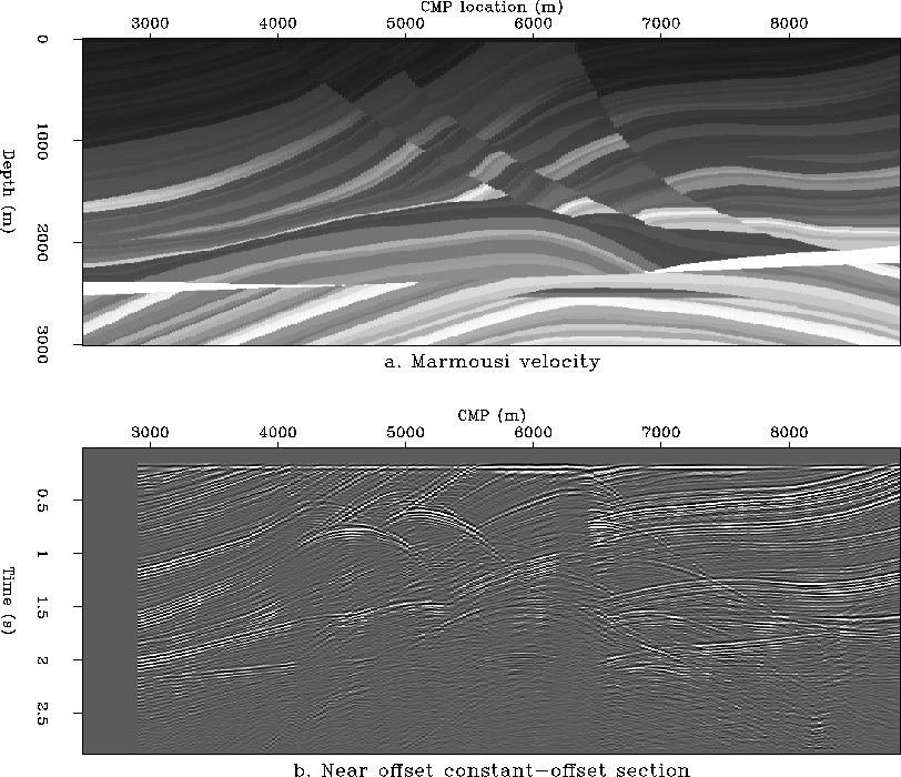
The complex velocity model,
with strong lateral velocity variations, is
shown in Figure ![[*]](http://sepwww.stanford.edu/latex2html/cross_ref_motif.gif) a. Figure
a. Figure ![[*]](http://sepwww.stanford.edu/latex2html/cross_ref_motif.gif) b
shows the near-offset section with a half-offset h=100 m.
b
shows the near-offset section with a half-offset h=100 m.
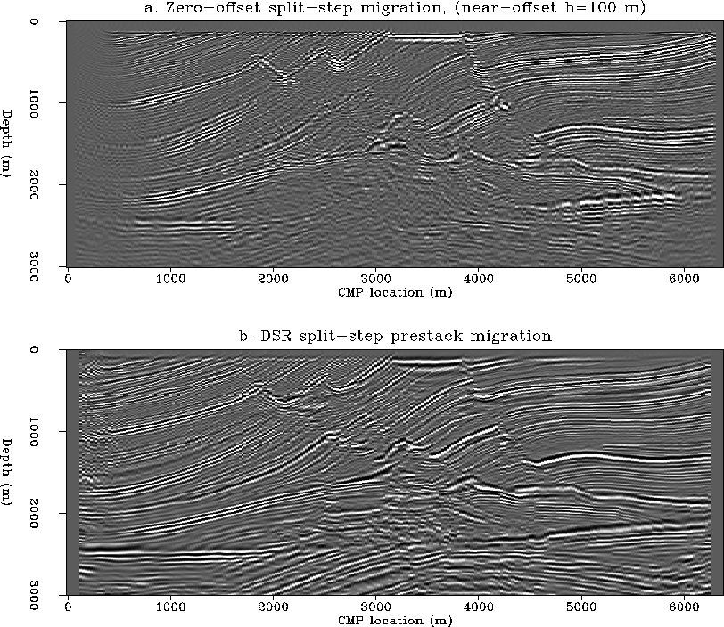
Figure ![[*]](http://sepwww.stanford.edu/latex2html/cross_ref_motif.gif) a shows the result of zero-offset
split-step migration applied to the near-offset section.
The full near offset is 200 meters (h=100 m).
Applying a zero-offset algorithm to a non-zero offset section
obviously introduces errors in the imaging results, and the
target area is poorly imaged. In comparison, the DSR split-step
prestack migration algorithm produces an excellent image of
the hydrocarbon trap, shown in Figure
a shows the result of zero-offset
split-step migration applied to the near-offset section.
The full near offset is 200 meters (h=100 m).
Applying a zero-offset algorithm to a non-zero offset section
obviously introduces errors in the imaging results, and the
target area is poorly imaged. In comparison, the DSR split-step
prestack migration algorithm produces an excellent image of
the hydrocarbon trap, shown in Figure ![[*]](http://sepwww.stanford.edu/latex2html/cross_ref_motif.gif) b.
b.
 |
 |
The size of the prestack migration dataset used was 720x256x64 and was increased to 1024x256x64 by zero padding for the fast Fourier transform. The prestack migration took about 20 minutes on a 1024x256x64 dataset. The prestack migration took about 20 minutes on our CM-5 when using the entire frequency spectrum (1024 frequencies). The runtime can be effectively cut by a factor of two by using only half of the total number of frequencies. My implementation also sums implicitly over the offset. By using the artifact reduction techniques described in Popovici (1993) and stationary phase tables, the algorithm can be modified to handle separate offsets.
CONCLUSIONS A very simple split-step modification to DSR prestack migration leads to a powerful migration algorithm that can handle strong lateral velocity variations. The new algorithm produces very good images of the Marmousi dataset and is computationally very efficient on our CM-5.
REFERENCES
![[*]](http://sepwww.stanford.edu/latex2html/prev_gr.gif)