 |
Figure 1 .
![[*]](http://sepwww.stanford.edu/latex2html/prev_gr.gif)
ABSTRACTI present a layer-stripping Kirchhoff migration algorithm which is capable of obtaining accurate images of complex structures by downward continuing the data and imaging from a lower datum. I use eikonal traveltimes in a Kirchhoff datuming algorithm for the downward continuation. After downward continuation, I perform Kirchhoff migration. The method alternates steps of datuming and imaging. Because traveltimes are computed for each step, the adverse effects of caustics, headwaves, and multiple arrivals do not develop. In principal, this method only requires the same number of traveltime calculations as a standard migration. Tests on the Marmousi data set produce excellent results. |
Kirchhoff migration is generally accepted to be the most efficient method of imaging 2-D and 3-D prestack seismic data. The Marmousi synthetic data set (Versteeg and Grau, 1991) has been a popular testbed for migration algorithms and many researchers have discovered that Kirchhoff algorithms using first-arrival traveltimes do a poor job of imaging the target zone (Audebert et. al., 1994b; Gray and May, 1993; Geoltrain and Brac, 1993). Even methods which calculate most energetic arrivals and estimate amplitude and phase do not always result in images which compare favorably with finite-difference shot-profile migration.
In their 1993 Geophysics article, Geoltrain and Brac ask the question ``Can we image complex structures with first-arrival traveltime?'' They conclude that they cannot, and that they should either ray trace to find the most energetic arrivals, or calculate multiple-arrival Green's functions. Nichols (1994) calculates band-limited Green's functions to estimate the most energetic arrivals. He estimates not only traveltime, but also amplitude and phase. My approach is simpler; by breaking up the complex velocity structure, I am able to calculate traveltimes in velocity models where finite-differencing the eikonal equation is valid. This results in images comparable to those obtained by Nichols' method and by shot-profile migration at a reduced computational cost.
Like most of the other researchers in the field, I test my method on the ever-popular Marmousi synthetic.
TRAVELTIME CALCULATION
Green's functions based on first-arrival traveltime calculation methods result in poor images in structurally complex areas. Several reasons have been given for this failure:
Complexity of velocity models and validity of high-frequency approximations can be defined in various ways. The larger the velocity model, the more variation there will tend to be and the more opportunity there will be for things to go wrong: There will be more opportunity for frequency components to separate, for headwaves to develop, and for triplications to occur.
 |
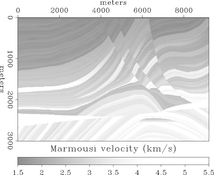
The Marmousi velocity model.
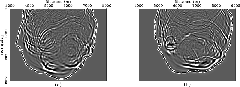
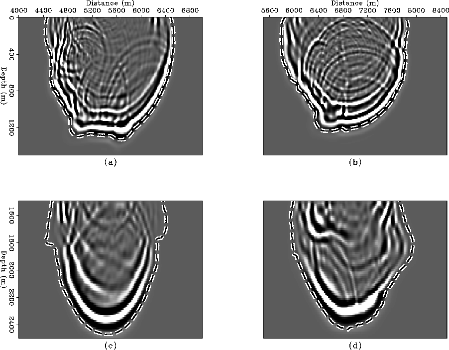
The Marmousi velocity model (Figure velfig) results in complex propagation paths where late energetic arrivals are not fit well by first-arrival finite-difference traveltimes. In Figure snap0, an acoustic modeling program was used to generate snapshots of the wavefield from two surface source locations in the Marmousi model. The corresponding contours of finite-difference traveltime at 1.05 s have been overlain. Clearly, the finite-difference traveltime contours do not always correspond to energetic portions of the wavefield. If these traveltimes were used for migration, the resulting image would suffer because parts of the summation trajectories would not correspond to energetic arrivals. By contrast, snapshots for the same source locations at an earlier time of 0.6 s (Figures snapdatuma and snapdatumb) show that the finite-difference traveltime curves overlay the high energy portions of the wavefields nicely. This is because there has not been enough time for adverse propagation effects to fully develop. Figures snapdatumc and snapdatumd are generated by starting the acoustic modeling and the finite-difference traveltime calculation from a depth of 1500 m. The 0.3 s contours correspond nicely to the high energy portions of the wavefields. There is some deviation in the shallow part of Figure snapdatumc, but for the most part the finite-difference traveltime contour fits the bulk of the acoustic energy pretty well. Overall, the contours in Figure snapdatum have not pulled away from the wavefield as they have in Figure snap0.
 |
 |
These properties of first-arrival traveltimes, and the observation that Kirchhoff migration using first-arrival traveltimes usually produces an acceptable image of the upper 1500 m of the Marmousi synthetic, motivated the development of the layer-striping method described here.
Throughout this study, I use a finite difference solution to the eikonal equation to generate traveltimes (van Trier and Symes, 1991). I use my Kirchhoff datuming algorithm (Bevc, 1993), and an industry standard Kirchhoff migration code to generate the results.
LAYER-STRIPPING KIRCHHOFF MIGRATION
The layer-stripping migration method can be thought of as a hybrid algorithm that incorporates some of the advantages of shot-profile migration with the efficiency of Kirchhoff migration. This is illustrated by Figures s-g through datum.
In shot-profile migration, shots and geophones are alternately downward continued through each depth level. Figure s-g illustrates this for one line of shots or geophones. It is evident that there are many propagation paths from the surface to the image point, therefore multiple arrivals are handled. The computation is performed for all frequencies.
By contrast, first-arrival Kirchhoff migration is performed by summing data over trajectories defined by the propagation paths illustrated in Figure kirch. There is only one path linking each surface position to the image point, therefore multiple arrivals are not handled. Although crossing paths are not illustrated here, they can occur.
The layer-stripping method is illustrated in Figure datum. It is a combination of Kirchhoff wave-equation datuming (Berryhill, 1979; Berryhill, 1984) and Kirchhoff migration. The computation proceeds as follows:
|
s-g
Figure 4 Propagation paths from the surface to an image point for shot profile migration. | 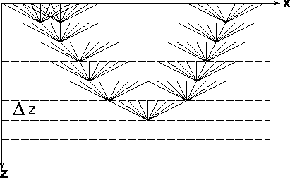 |
|
kirch
Figure 5 Propagation paths from the surface to an image point for Kirchhoff downward continuation. |  |
|
datum
Figure 6 Propagation paths from the surface to a depth point for layer-stripping Kirchhoff downward continuation. |  |
MARMOUSI EXAMPLE
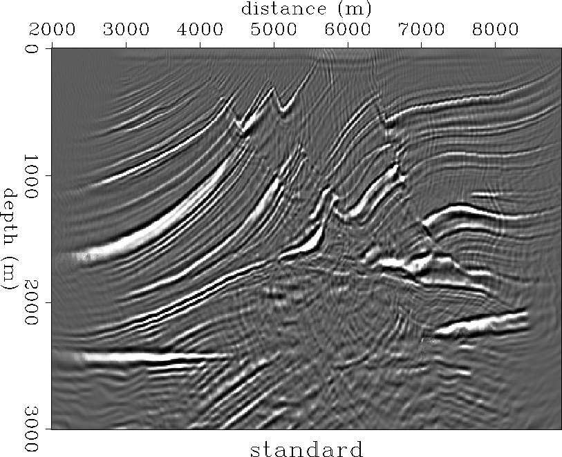
Figure eikmarmcggmig is the result of an industry standard Kirchhoff migration of the Marmousi synthetic using eikonal traveltimes. The upper portion is well imaged; however, the anticlinal structure below 2200 m and the target zone at a lateral position of about 6500 m and depth of 2500 m is not imaged.
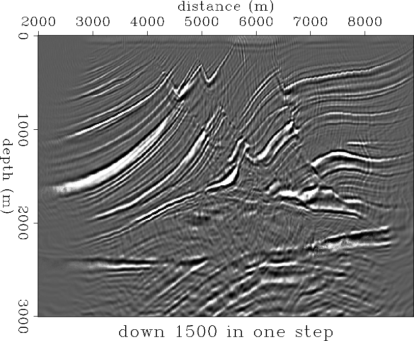
Figure mergecggall1500 is generated by downward continuing the data to a depth of 1500 m in one datuming step. The downward continued data are then migrated and combined with the previous image of the upper 2000 m. The anticlinal structure and the target are now clearly imaged.
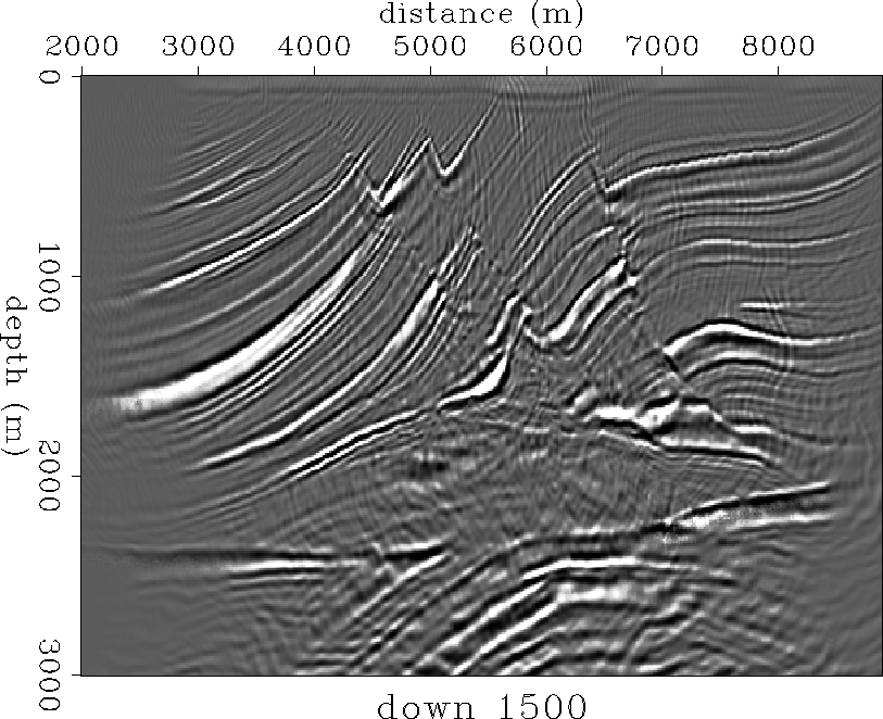
Continuing the data to 1500 m in three steps of 500 m each, results in an even crisper image of the anticline and the target (Figure mergecgg1500). In both of these images, the events which unconformably define the top of the anticline, the anticline events themselves, and the target events, are clearly imaged.
 |
 |
 |
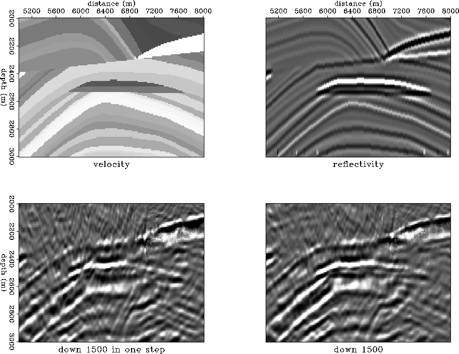
In Figure targref, I compare the images in the vicinity of the target zone to the velocity model and a filtered reflectivity model which represents the desired image. Both images compare favorably to the desired reflectivity. The image obtained by downward continuing the data in three steps of 500 m is superior since the events display better lateral continuity and the image is clearer. This is because the traveltimes calculated for each of the 500 m steps are simpler and better behaved than the traveltimes calculated for one step of 1500 m.
 |
CONCLUSION I obtain images comparable to shot-profile migration results by combining wave-equation datuming and Kirchhoff migration into a layer-stripping migration method. In this case, eikonal traveltimes produce satisfactory images because the velocity model is subdivided and traveltimes are calculated under conditions where finite-differencing the eikonal equation is valid. By dividing the imaging problem in this way, the traveltimes are better behaved and some multiple arrivals are accounted for.
REFERENCES
![[*]](http://sepwww.stanford.edu/latex2html/prev_gr.gif)