
![[*]](http://sepwww.stanford.edu/latex2html/prev_gr.gif)


Next: About this document ...
Up: Table of Contents
4-D seismic monitoring of an active steamflood
David E. Lumley
ABSTRACT
3-D migrations of time-lapse seismic monitor data acquired
during steam injection show dramatic
and complex changes in the reservoir zone over a wide area, compared to
baseline seismic data recorded prior to steam injection.
Anticipated large decreases in seismic P-wave velocity Vp
near the injection well correlate with the presence of a
hot desaturated steam zone. Unanticipated large increases in Vp
in an annulus around the steam zone may correspond to a high-pressure
cold oil front, in which residual free gas in pore space crosses the bubble
point and dissolves into liquid oil.
Horizontal and vertical anisotropy in flow directions inferred
from these seismic observations correlate with two temperature monitor wells,
and in situ measurements of upper and lower reservoir permeability.
Since the pressure front propagates out from the injector an order
of magnitude faster than either the thermal or steam fronts,
monitoring it may be useful for predicting future fluid-flow paths of
heated oil, months in advance of actual production.
|
INTRODUCTION
The steamflood process is a common method of enhanced oil recovery (EOR)
in heavy oil reservoirs. However, steam flow directions, rates
and sweep efficiency can be unpredictable in the presence of reservoir
heterogeneity. This uncertainty can lead to expensive changes in injection
well placement, intervals of perforation, and surface steam facility planning.
Spatial changes in pressure, temperature and fluid saturation in the
reservoir during steamflooding can cause dramatic changes in rock physics
properties, and hence seismic wavefield attributes, e.g.,
Ito et al. ,
Wang and Nur .
In principle, detecting and
measuring changes in the seismic response as a function of time can lead to
a better understanding of the steamflood fluid-flow dynamics, and in turn, can
help optimize the production strategy for an EOR project
().
Although the concept of time-lapse seismic reservoir monitoring is relatively
new, a few notable pilot projects have been attempted at EOR steam sites.
Pullin et al. collected two 3-D seismic
surveys before and after a
steam pilot at an Athabasca tar sands reservoir site. By comparing time delay
and amplitude attenuation maps between the two stacked surveys, they were
able to qualitatively map the location of heated versus unheated zones.
Their observed vertical traveltime delays and attenuations through heated
sections of the reservoir compared reasonably well with rock physics
studies of the predicted thermal effects on seismic data.
Eastwood et al.
performed a similar analysis on a 3-D seismic monitor
of an Alberta cyclic steam stimulation (CSS) project. They used
two 3-D seismic surveys recorded at separate production and injection cycles,
integrated with crosswell data, thermal reservoir simulations, and
rock physics measurements. They were able to fit the magnitude of
changes between two surveys, but less so the spatial distribution of changes.
Non-steam seismic monitoring projects of interest include an in-situ
combustion study by Greaves and Fulp ,
and a gascap monitoring study in the Oseberg field by
Johnstad et al. .
Currently, an ongoing 4-D seismic monitoring experiment is being conducted to
monitor a steamflood in a shallow heavy oil reservoir in the Duri field,
Indonesia. An excellent overview of the experiment and first interpretation
of the field data has been presented by Bee et al. .
Two baseline surveys were acquired before steam injection to demonstrate
data repeatability. Five monitor surveys have been recorded so far at
an average of 4 month intervals, ranging from 2 to 19 months after steam
injection was initiated. Two temperature monitor wells are available,
and six core samples were taken from the injector borehole pre-steam at
various levels of the reservoir zone. I analyze this data set in collaboration
with Bee et al. to understand the complex seismic changes observed between
the repeated 3-D surveys in terms of changing reservoir parameters and
fluid flow. In particular, I attempt to explain the complex seismic monitor
phenomena by integrating a simple model of steamflood fluid-flow with
rock physics measurements, finite-difference seismogram modeling,
and 3-D prestack seismic imaging.
FIELD DESCRIPTION
Oil production
The 4-D seismic monitor data are recorded in the Duri Field, Indonesia.
Bee et al. review the field's history,
current production, and describe the 4-D experiment and preliminary
interpretation. The Duri Field contains 5.3 billion barrels (bbls)
of original oil in place (OOIP). Primary production
was expected to produce only about 400 million bbls, 8% of OOIP,
because the Duri oils are very viscous (API gravity is 22 degrees).
With steamflooding, about 60% of OOIP is expected to be recovered,
representing an additional 2.7 billion bbls of oil over primary production.
Currently, about 40% of the field is undergoing steamflooding.
The first steamflood patterns were drilled in 1985 and have increased the
field production from about 40,000 barrels per day (BPD) to currently
over 285,000 BPD. Over $1.2 billion has been invested in steamflooding
to date, and the project is expected to expand to completion for
another 25 years. If seismic monitoring can increase production by
only 1% of OOIP, an extra 53 million bbls of oil will be gained.
Reservoir quality
The main oil reservoirs are in very unconsolidated sands and silts
at depth of 100-200 meters. Porosities and permeabilities
are high and range from 30-38% and 1-8 darcies respectively.
Oil saturation ranges from 29-69%, with a residual gas saturation
of about 10% due to pressure drawdown during primary production.
Duri oil is very heavy and viscous with an API gravity of 22, and
viscosities of 100-1000 cp. Clay layers can cause flow barriers,
and heterogeneity can make steam flow directions unpredictable.
For these reasons, a 4-D seismic monitor experiment was conducted
on a small steam injection pattern to see if vertical and lateral
steam flow could be mapped from seismic.
Steamflood pattern
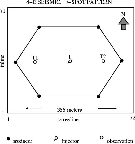
Figure ![[*]](http://sepwww.stanford.edu/latex2html/cross_ref_motif.gif) shows a diagram of a single ``7-spot'' steam
injection well pattern. The surface area of the 4-D seismic coverage is
outlined by the outer box, and is 355 m on a side. The 7-spot is
composed of six producing wells (black circles) connected in a hexagon,
with the seventh well being the steam injector in the center (open circle
with arrow).
Additionally, two temperature observation wells (open circles)
are located on either side of the injector.
shows a diagram of a single ``7-spot'' steam
injection well pattern. The surface area of the 4-D seismic coverage is
outlined by the outer box, and is 355 m on a side. The 7-spot is
composed of six producing wells (black circles) connected in a hexagon,
with the seventh well being the steam injector in the center (open circle
with arrow).
Additionally, two temperature observation wells (open circles)
are located on either side of the injector.
7-spot
Figure 1 Duri 4-D seismic coverage over
a single 7-spot production pattern. Steam injection well is
at the center, flanked by two temperature monitor wells.

4-D SEISMIC FIELD DATA
Seismic acquisition
Several 3-D seismic data sets have been acquired over the injector
pattern of Figure ![[*]](http://sepwww.stanford.edu/latex2html/cross_ref_motif.gif) . Two baseline surveys were collected
prior to steam injection for comparison with surveys taken during
steam injection. The repeatability of the seismic measurements
was confirmed with two baseline surveys to ensure that changes in repeated
3-D surveys were due to subsurface conditions, not acquisition-related
variations.
. Two baseline surveys were collected
prior to steam injection for comparison with surveys taken during
steam injection. The repeatability of the seismic measurements
was confirmed with two baseline surveys to ensure that changes in repeated
3-D surveys were due to subsurface conditions, not acquisition-related
variations.
Each 3-D survey consists of 301 shots fired into a fixed array of
480 receivers. Each shotpoint consists of a small dynamite charge (50 g)
fired in a shot hole at 45 ft. depth. Each receiver is a single
hydrophone immersed in water at 20 ft. depth. Frequencies in the data
exceed 200 Hz at a 1 ms sample interval. The maximum offset in the data
is 480 m, with a good range of offset and azimuthal coverage.
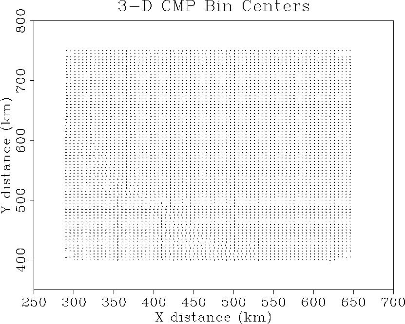
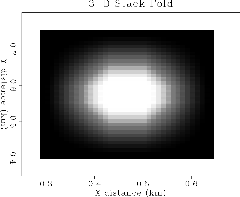
Maximum fold is 80 in the center of the pattern. A complete 3-D
survey can be acquired in one day. Figure ![[*]](http://sepwww.stanford.edu/latex2html/cross_ref_motif.gif) shows the bin centers for the 3-D survey, and Figure
shows the bin centers for the 3-D survey, and Figure ![[*]](http://sepwww.stanford.edu/latex2html/cross_ref_motif.gif) shows the fold chart.
shows the fold chart.
To date, five repeated seismic monitor surveys have been obtained with
identical acquisition parameters. Shot and receiver holes were predrilled
and reoccupied for each monitor survey. Both sets of holes are cased down
to just above the source or shot depth. Dynamite charges were lowered
and tamped with sand for each survey, and the small charge size was
chosen for good bandwidth and negligible hole damage.
Hydrophones were lowered into each receiver hole and filled with water.
Repeat surveys were acquired at intervals ranging from two months
after steam injection, to 19 months after steam injection, with an
average 4 month repeat interval. In this paper, I will concentrate
on the baseline survey and the second monitor after 5 months of steam
injection.
cmpbins
Figure 2 3-D survey CMP bin center locations.
Seismic ``inlines'' are horizontal, ``crosslines'' are vertical.


 stkfold
Figure 3 3-D survey stack fold.
The fold is about 2 at the survey edges, and a maximum of
80 in the center white patch.


Field data
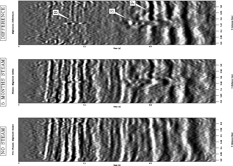
Figure ![[*]](http://sepwww.stanford.edu/latex2html/cross_ref_motif.gif) shows 3-D stacked inline sections of the
baseline, monitor and the difference between the two.
The location of the inline sections passes through the two
temperature observation wells and the steam injector.
Figure
shows 3-D stacked inline sections of the
baseline, monitor and the difference between the two.
The location of the inline sections passes through the two
temperature observation wells and the steam injector.
Figure ![[*]](http://sepwww.stanford.edu/latex2html/cross_ref_motif.gif) shows the same display of 3-D
migrated inline data. Figure
shows the same display of 3-D
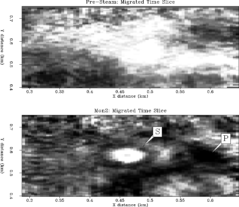
migrated inline data. Figure ![[*]](http://sepwww.stanford.edu/latex2html/cross_ref_motif.gif) shows a time slice at
204 ms before and after steam injection. The top of the main reservoir
is at about 160 ms, and the base is just below 200 ms. Steam had been
injected continuously into this zone for five months at the time
of this monitor survey.
shows a time slice at
204 ms before and after steam injection. The top of the main reservoir
is at about 160 ms, and the base is just below 200 ms. Steam had been
injected continuously into this zone for five months at the time
of this monitor survey.
The inline stacks and migrations show that data above the reservoir
(less than 150 ms) is highly repeatable. The only major difference above the
reservoir is the effect of the borehole region being heated by
a possible steam leak causing
time sag in the center of the profile. This is most notable in the
migrated section of Figure ![[*]](http://sepwww.stanford.edu/latex2html/cross_ref_motif.gif) , and labeled with a ``B''.
The stacked sections show a large diffraction response, labeled ``D'',
which has an apex at about 200 ms, at the base of the reservoir.
Weaker diffraction responses are less visible at the top of the reservoir
around 160 ms. These diffractions are probably due to the steam zone,
as will be demonstrated in the seismic modeling section of this paper.
, and labeled with a ``B''.
The stacked sections show a large diffraction response, labeled ``D'',
which has an apex at about 200 ms, at the base of the reservoir.
Weaker diffraction responses are less visible at the top of the reservoir
around 160 ms. These diffractions are probably due to the steam zone,
as will be demonstrated in the seismic modeling section of this paper.
The migrated sections in Figure ![[*]](http://sepwww.stanford.edu/latex2html/cross_ref_motif.gif) show that major
changes in the seismic data have occurred near the injection well (center)
within the reservoir zone from 160-200 ms. The bright reflections
labeled ``S'' are probably due to presence of steam, and cause
time sag (velocity decrease) below the reservoir at the injector site.
A very anomalous polarity change has been caused by the process of
steamflooding, and is labeled ``P'' in the sections. This strong
polarity change is visible in both the stacked and migrated sections,
and is asymmetric in that it occurs on one side of the injector,
but not the other. Additionally, there appear to be some time
pull-ups (velocity increase) very close to the injector,
which give a sinusoidal
shape to the reflector at 200 ms, most visible in the monitor migration.
The difference sections show that within the reservoir zone
only a narrow width of about 50 m is affected by steam injection.
However, below the reservoir base of 200 ms, large changes have occurred
in the seismic data for a full 350 m out to both edges of the survey.
show that major
changes in the seismic data have occurred near the injection well (center)
within the reservoir zone from 160-200 ms. The bright reflections
labeled ``S'' are probably due to presence of steam, and cause
time sag (velocity decrease) below the reservoir at the injector site.
A very anomalous polarity change has been caused by the process of
steamflooding, and is labeled ``P'' in the sections. This strong
polarity change is visible in both the stacked and migrated sections,
and is asymmetric in that it occurs on one side of the injector,
but not the other. Additionally, there appear to be some time
pull-ups (velocity increase) very close to the injector,
which give a sinusoidal
shape to the reflector at 200 ms, most visible in the monitor migration.
The difference sections show that within the reservoir zone
only a narrow width of about 50 m is affected by steam injection.
However, below the reservoir base of 200 ms, large changes have occurred
in the seismic data for a full 350 m out to both edges of the survey.
The time slices at 204 ms in Figure ![[*]](http://sepwww.stanford.edu/latex2html/cross_ref_motif.gif) show
dramatic change at the base of the reservoir. A bright reflective disk
with a diameter of 50 m, labeled ``S'', is centered about the injector,
surrounded by a thin (20 m) dark gray annulus. A larger black
``front'' extends
out to the edge of the survey to the east and south, labeled ``P'',
and corresponds to the polarity reversal seen in the inline sections.
show
dramatic change at the base of the reservoir. A bright reflective disk
with a diameter of 50 m, labeled ``S'', is centered about the injector,
surrounded by a thin (20 m) dark gray annulus. A larger black
``front'' extends
out to the edge of the survey to the east and south, labeled ``P'',
and corresponds to the polarity reversal seen in the inline sections.
Questions
Since reflections from the region above the top of
the reservoir are seen to be very repeatable in both surveys, we can be
certain that changes in and below the reservoir are due to the steamflood
process. These dramatic changes in seismic data during 5 months of
steam injection raise many interesting questions.
- Do the bright reflections and time sag in the reservoir
indicate the presence of steam, or merely hot fluid?
- Should we be able to distinguish separate fluid-fronts
of water, oil and steam?
- What could be causing time pull-up (velocity increase?)
near the injector?
- What is the explanation for the large polarity reversal
along the base of reservoir reflection, and its asymmetry?
- Why are changes within the reservoir confined to a width
of only 50 m, whereas changes below the reservoir extend
at least 350 m out to the edge of the survey area?
In the following sections, I attempt to answer some of these questions
by carefully considering steamflood fluid-flow physics, rock physics
measurements, and finite-difference seismic modeling in comparison
with these data displays.
inline-stks-ann
Figure 4 3-D stacked inline
sections: before steam injection (left), during steam (center),
and the difference (right). ``S'' marks a steam zone,
``D'' marks a diffraction, and ``P'' marks a polarity reversal.
![[*]](http://sepwww.stanford.edu/latex2html/movie.gif)


 inline-migs-ann
Figure 5 3-D migrated inline
sections: before steam injection (left), during steam (center),
and the difference (right). ``S'' marks a steam zone,
``B'' marks borehole heating by a possible steam leak,
and ``P'' marks a polarity reversal.
![[*]](http://sepwww.stanford.edu/latex2html/movie.gif)


 tslice-migs-ann
Figure 6 3-D migrated time slices
at the base of the reservoir (204 ms): before steam injection (top),
and after 5 months of steam injection (bottom). ``S'' marks the
steam zone, and ``P'' marks the polarity reversal associated
with a possible high-pressure front.


RESERVOIR FLUID FLOW
Reservoir conditions
The seismic monitor data were recorded over a 7-spot steamflood
pattern (six producing wells in a hexagon plus one central injector),
and fits within a square of about 350 m on a side. The main reservoir
zone is at approximately 200 m depth and consists of very unconsolidated
sands, silts and clays. Porosity and permeability range from 37-42% and
1.2-8.5 Darcy respectively. The heavy oil has an API gravity of 22 degrees,
and viscosities of 150-1000 cp. Oil saturations range from 29-69%,
and there is a residual gas saturation of about 10% in pore space caused
by previous pressure depletion. The overburden pressure is 530 psi,
and pore pressures range from 100 psi (pre-steam) to 350 psi at the injector
during steamflooding. Reservoir temperatures range from 100 F (ambient)
to 350 F (steam).
Steamflood model
It is convenient to have an idealized model of the steamflood
fluid-flow physical properties in order to make some
predictions about the nature of rock physics and seismic responses
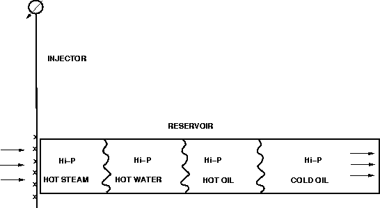
during steam injection. I consider four separate fluid zones
associated with the steamflood:
(1) a high-pressure, low-temperature heavy oil zone, (2) a high-pressure,
high-temperature heavy oil zone, (3) a high-pressure, high-temperature water
zone, and (4) a high-pressure, high-temperature desaturated steam zone.
This simple model is schematically diagrammed in Figure ![[*]](http://sepwww.stanford.edu/latex2html/cross_ref_motif.gif) .
This model is slightly more complicated than the conventional block
model of a heated zone and a cold zone, but does not try to incorporate
the complexity of mixed fluid phases, emulsions, fingering, gravity
overrides, etc., as described by Lake for example.
.
This model is slightly more complicated than the conventional block
model of a heated zone and a cold zone, but does not try to incorporate
the complexity of mixed fluid phases, emulsions, fingering, gravity
overrides, etc., as described by Lake for example.
This model is qualitatively supported by common observations.
In well-to-well pressure transient tests, it takes on the order of
hours to days for a pressure pulse at one well to propagate to
an adjacent well. Pressure is transmitted through the fluid
in the connected pore space at a relatively fast rate because it
does not require fluid transport or conduction to diffusively propagate.
On the other hand, temperature monitoring wells show that thermal
fronts take on the order of weeks to months to propagate similar
well-to-well distances. This is because heat transfer must occur through
a combination of conduction through the rock matrix and convective transport
of heated fluids through the permeable pore space, both of which
tend to be relatively slow processes. A desaturated steam front
propagates even slower than a thermal front, because of the additional work
required to drive fluids out of pore space.
Therefore, to first approximation, a steam-induced pressure front
will travel about one order of magnitude faster than the associated
thermal front. This implies that to a distant observer in the reservoir,
the first front to arrive will be a high-pressure cold oil front.
The next zone to arrive will be high-pressure heated oil as the
thermal effects propagate outward from the steam injector.
A hot water zone of condensed steam follows and heats the oil
ahead of it, lowering the oil viscosity enough to displace oil
with water as it propagates radially away from the injector.
Finally, closest to the injector, a hot steam zone with negligible
fluid saturation exists as the heat source that drives the total
fluid-flow process. It is likely that the steam zone would reach
steady-state equilibrium conditions fairly quickly and maintain a stable
but slowly expanding disk of growth. In contrast, the pressure front
is likely to be large and may propagate rapidly to remote sections of
the reservoir. The hot oil and water zones are probably intermediate
in size between the steam and high-pressure cold zones.
steam-fronts
Figure 7 An idealized model of steamflood
fluid flow. A rapid high-pressure cold front is expected
to lead the injector flow, trailed by hot oil, hot water
and hot steam zones. The relative dimensions of each zone
may not be to scale, and complexities such as mixed phases
and gravity overrides are neglected.

ROCK PHYSICS
Core measurements
Rock physics core measurements were made by Zhijing Wang at Chevron's
research facility. Six core samples were taken from the injection well
location prior to steamflooding. The samples range from clean fine sand,
to clay/silt/sand. The samples show highly unconsolidated sedimentary
material. Some samples show coarse sand pockets which might represent
potential high-porosity, high-permeability micro channels.
The core samples were found to be very sensitive to pressure and
temperature conditions. Vp decreases of 10-19% were measured for
temperature increases from 25 C to 177 C at fixed overburden pressure (530 psi)
for core samples saturated with 30-70% oil.
An additional Vp decrease of 12-28%
for the same temperature increase was measured on samples in
which fluid had been replaced with steam (gas).
At fixed overburden pressure and temperature, Vp decreases 3-9%
as pore pressure increases
from 100 psi to 400 psi in saturated samples. This is due to grain matrix
compaction alone, not any phase change in the pore fluid.
The effect of a decrease in gas saturation from 10% to 0% results
in a velocity increase of 19-26%. An increase in gas saturation from
10% to 25% or more results in a 10-15% decrease in velocity.
Steamflood properties
Based on the simple steamflood model of Figure ![[*]](http://sepwww.stanford.edu/latex2html/cross_ref_motif.gif) ,
and the core measurement data at Duri,
some rock physics analysis can be made to give approximate
estimates of seismic velocity changes that may occur in the reservoir
during the steamflood. These rock physics predictions give an indication
as to what might be observed in time-lapse 3-D surface seismic monitor
surveys. The effects of pressure, temperature, gas/fluid saturation,
and hydrocarbon P-T phase diagrams are considered for
each of the four steamflood fluid-flow zones described previously.
,
and the core measurement data at Duri,
some rock physics analysis can be made to give approximate
estimates of seismic velocity changes that may occur in the reservoir
during the steamflood. These rock physics predictions give an indication
as to what might be observed in time-lapse 3-D surface seismic monitor
surveys. The effects of pressure, temperature, gas/fluid saturation,
and hydrocarbon P-T phase diagrams are considered for
each of the four steamflood fluid-flow zones described previously.
Hi-pressure cold oil front
As the Duri core measurements show,
P-wave velocity Vp varies with differential
pressure, which is the difference between overburden and pore pressure.
Overburden pressure is about 530 psi in the main Duri reservoir.
Ambient pore pressure before steam injection is about 100 psi
due to depressurization during primary production.
During steam injection, the pore pressure at the injector may be as
high as 350 psi, and would decay logarithmically with radial distance
from the injector. This pore pressure increase of 200-300 psi due to
steam injection decreases the P-wave velocity by about 3-9%
depending on the matrix consolidation of the core sample.
Additionally, the Duri reservoir is initially below bubble point,
since there is residual gas saturation of about 10%.
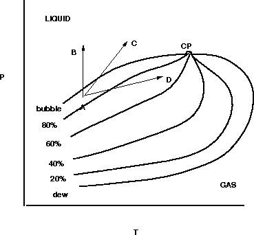
The bubble point is defined as the contour in P-T phase space where
decreasing the pressure at fixed temperature will cause 100% liquid oil
to begin forming gas bubbles, as shown in Figure ![[*]](http://sepwww.stanford.edu/latex2html/cross_ref_motif.gif) .
Duri engineers estimate that an increase of only 10 psi at 100 F is
sufficient to dissolve the free gas back into liquid phase.
Therefore, the initial 10% free gas in the reservoir is dissolved back
into liquid oil as the high-pressure front propagates. This situation is
depicted by the path A-B in the hydrocarbon phase diagram of
Figure
.
Duri engineers estimate that an increase of only 10 psi at 100 F is
sufficient to dissolve the free gas back into liquid phase.
Therefore, the initial 10% free gas in the reservoir is dissolved back
into liquid oil as the high-pressure front propagates. This situation is
depicted by the path A-B in the hydrocarbon phase diagram of
Figure ![[*]](http://sepwww.stanford.edu/latex2html/cross_ref_motif.gif) : an increase in pressure at fixed temperature
crosses the bubble point line ().
: an increase in pressure at fixed temperature
crosses the bubble point line ().
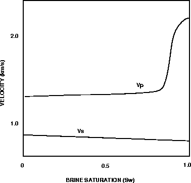
The change from an oil saturation of 0.9 to 1.0 can cause a dramatic
increase in Vp, as first described by
Domenico .
Figure ![[*]](http://sepwww.stanford.edu/latex2html/cross_ref_motif.gif) shows Domenico's experimental results that Vp can
increase by at least 10% in this regime of fluid saturation contrast.
Duri core measurements show that saturated samples increase in velocity
by about 26% at 200 psi pore pressure. The larger change compared to
Domenico's results is probably attributed to the highly unconsolidated
nature of Duri reservoir sands.
shows Domenico's experimental results that Vp can
increase by at least 10% in this regime of fluid saturation contrast.
Duri core measurements show that saturated samples increase in velocity
by about 26% at 200 psi pore pressure. The larger change compared to
Domenico's results is probably attributed to the highly unconsolidated
nature of Duri reservoir sands.
Combining the effects of pore pressure increase and gas saturation
decrease across the bubble point, a net velocity increase of at least
17-23% is
expected in the high-pressure cold oil front compared to initial
reservoir conditions, as shown in Figure ![[*]](http://sepwww.stanford.edu/latex2html/cross_ref_motif.gif) .
.
hc-phase
Figure 8 Hydrocarbon phase diagram with contours
of liquid oil saturation relative to gas. CP is the critical point,
P-T is the pressure-temperature plane (after Dake, 1978).
 vp-sat
Figure 9 Vp and Vs versus brine saturation
for Ottawa sandstone at a differential pressure of 10 MPa
(after Domenico, 1977).

Hot oil zone
Wang and Nur
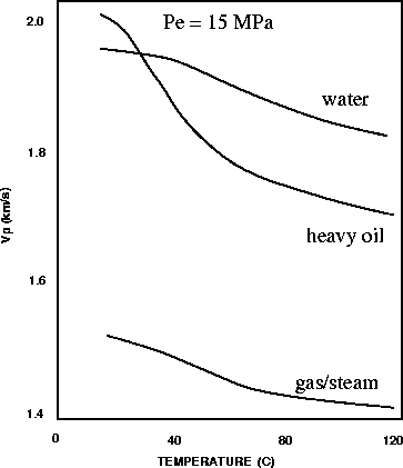
performed experiments which showed the effects of
temperature and oil/water/gas saturation on Ottawa sandstone,
as diagrammed in Figure ![[*]](http://sepwww.stanford.edu/latex2html/cross_ref_motif.gif) .
Assuming hot oil displaces original cold oil, Figure
.
Assuming hot oil displaces original cold oil, Figure ![[*]](http://sepwww.stanford.edu/latex2html/cross_ref_motif.gif) shows that
this effect can cause Vp to decrease by about 15%.
This compares well with Duri measurements of velocity decreases
on the order of 10-19% for a 150 C temperature increase.
This accompanies a velocity decrease of 3-9% for a pore pressure
increase which softens the pores.
shows that
this effect can cause Vp to decrease by about 15%.
This compares well with Duri measurements of velocity decreases
on the order of 10-19% for a 150 C temperature increase.
This accompanies a velocity decrease of 3-9% for a pore pressure
increase which softens the pores.
However, when both pressure and temperature increase, the
gas saturation level may also change. To predict the latter, the bubble
point pressure needs to be known for the reservoir oil as a function
of temperature, which is the uppermost contour in Figure ![[*]](http://sepwww.stanford.edu/latex2html/cross_ref_motif.gif) .
Without knowing the exact shape of the phase space, an increase
in both P and T can lead to total gas dissolution (path A-C), or can
result in an increase in gas saturation (path A-D).
Normally, one would expect
the bubble point to increase slowly with temperature, such that
a large pore pressure increase from 100 psi to 300 psi at hot oil
temperatures of about 100 C would reduce the gas saturation, or
totally dissolve it (path A-C). This would again increase the
velocity by about 22% at 200 psi pore pressure due to the Domenico effect
as shown Figure
.
Without knowing the exact shape of the phase space, an increase
in both P and T can lead to total gas dissolution (path A-C), or can
result in an increase in gas saturation (path A-D).
Normally, one would expect
the bubble point to increase slowly with temperature, such that
a large pore pressure increase from 100 psi to 300 psi at hot oil
temperatures of about 100 C would reduce the gas saturation, or
totally dissolve it (path A-C). This would again increase the
velocity by about 22% at 200 psi pore pressure due to the Domenico effect
as shown Figure ![[*]](http://sepwww.stanford.edu/latex2html/cross_ref_motif.gif) .
.
The net effect of temperature increase, pore pressure increase
and some reduction in gas saturation
might make a net velocity change of about -6% to +9% in the hot oil zone,
as shown in Figure ![[*]](http://sepwww.stanford.edu/latex2html/cross_ref_motif.gif) . These values suggest that the oil zone
could be accompanied by either a small velocity increase or decrease,
and therefore might be seismically transparent.
. These values suggest that the oil zone
could be accompanied by either a small velocity increase or decrease,
and therefore might be seismically transparent.
Hot water zone
The hot water zone should have a simpler physical behavior compared
to the case of hot/cold high-pressure oil at or near the bubble point.
In this case, both hot oil and any residual gas saturation is largely
driven out by a hot water bank. The Vp contrast should be similar
to moving from the cold oil curve to the hot water curve in Figure
![[*]](http://sepwww.stanford.edu/latex2html/cross_ref_motif.gif) , which suggest a small velocity decrease of about 5%.
This accompanies the velocity decrease of 3-9% due to pore pressure
increase softening the pores.
Adding in the effect of decreased gas saturation causing a 22% increase
in velocity, a net velocity increase of
about 10-16% is expected in the hot water zone,
as shown in Figure
, which suggest a small velocity decrease of about 5%.
This accompanies the velocity decrease of 3-9% due to pore pressure
increase softening the pores.
Adding in the effect of decreased gas saturation causing a 22% increase
in velocity, a net velocity increase of
about 10-16% is expected in the hot water zone,
as shown in Figure ![[*]](http://sepwww.stanford.edu/latex2html/cross_ref_motif.gif) .
.
Steam zone
When the steam zone arrives, nearly all fluid is driven out of the
pore space, and is the primary mechanism for driving the hot water
zone forward. Figure ![[*]](http://sepwww.stanford.edu/latex2html/cross_ref_motif.gif) shows that the change from
initial cold oil to hot steam causes a dramatic decrease in Vp by
about 30%. Note that about 25% of this decrease is due to
the gas saturation change effect, and only a a further decrease of
5% is added by the thermal effect.
The Duri core measurements show that the increased temperature causes
a 10% decrease in velocity. The gas saturation increase from an
initial 10% to greater than 25% causes a further velocity decrease of 10%.
The pore pressure increase causes an additional 3-9% decrease in velocity.
The net effect is an approximate 23-30% velocity decrease
in the steamed zone, as shown in Figure
shows that the change from
initial cold oil to hot steam causes a dramatic decrease in Vp by
about 30%. Note that about 25% of this decrease is due to
the gas saturation change effect, and only a a further decrease of
5% is added by the thermal effect.
The Duri core measurements show that the increased temperature causes
a 10% decrease in velocity. The gas saturation increase from an
initial 10% to greater than 25% causes a further velocity decrease of 10%.
The pore pressure increase causes an additional 3-9% decrease in velocity.
The net effect is an approximate 23-30% velocity decrease
in the steamed zone, as shown in Figure ![[*]](http://sepwww.stanford.edu/latex2html/cross_ref_motif.gif) .
.
vp-temp
Figure 10 Vp measurements as a function of
temperature and saturation with air, water and heavy crude
in Ottawa sandstone (after Wang and Nur, 1988).
 steam-dIp
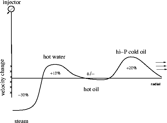
Figure 11 Predicted steamflood P-wave velocity
changes compared to initial reservoir conditions as a function of
dimensionless radial distance.

Velocity contrast profile
Figure ![[*]](http://sepwww.stanford.edu/latex2html/cross_ref_motif.gif) shows the predicted velocity contrast profile
in the radial direction away from the injector, obtained by combining the
rock physics results above. An impedance profile should look similar
since density changes will be approximately the same polarity as velocity
changes within each front. The rapidly outward-propagating
pressure front leads the thermal fronts,
and if the reservoir is initially just below the
bubble point pressure, the pressure front will appear seismically
as an increase in Vp by about 20%,
marked by velocity time pull-ups and a positive reflection coefficient.
shows the predicted velocity contrast profile
in the radial direction away from the injector, obtained by combining the
rock physics results above. An impedance profile should look similar
since density changes will be approximately the same polarity as velocity
changes within each front. The rapidly outward-propagating
pressure front leads the thermal fronts,
and if the reservoir is initially just below the
bubble point pressure, the pressure front will appear seismically
as an increase in Vp by about 20%,
marked by velocity time pull-ups and a positive reflection coefficient.
The thermal fronts are likely to lag behind the
leading pressure front by many months of steam injection. The
outermost thermal front is likely to contain hot oil and be
nearly seismically transparent, since it can have either a small
velocity increase or decrease of about 6-9%.
Just behind the hot oil front, a hot water front may exist.
It represents a velocity increase of 10-16% if the initial
10% gas saturation is driven away. Finally, a small stable steam zone
should surround the injector, perhaps growing in diameter at a very
slow rate. This steam zone has a net decrease in Vp of about 23-30%
and should be very visible in the seismic monitor data by strong
velocity pull-down and very bright negative reflection coefficient polarity.
SEISMIC MODELING
Combining the steamflood model and rock physics analysis,
I now show some finite-difference seismogram modeling
to examine what the seismic response to steamflooding might look like.
I show simple velocity models of the steamflood, wavefield snapshots,
shot gathers, and plane-wave stacks.
Velocity models
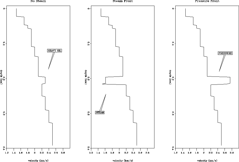
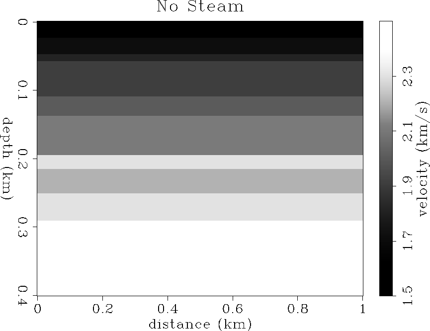
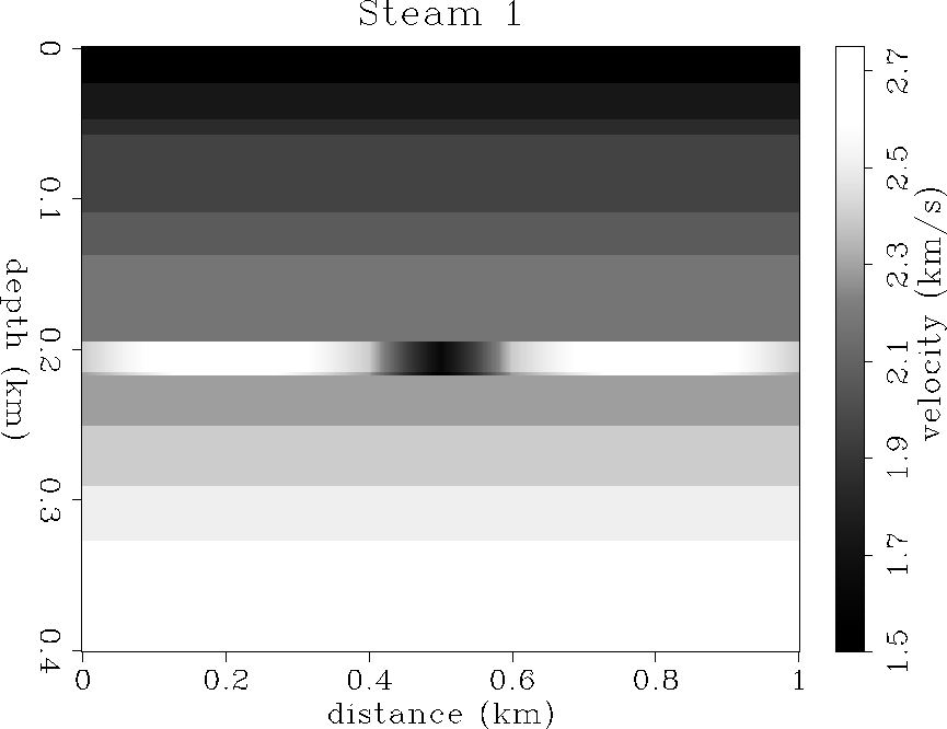
Figure ![[*]](http://sepwww.stanford.edu/latex2html/cross_ref_motif.gif) shows three 1-D velocity profiles. Each one is
identical except for the reservoir zone containing either: original cold oil,
steam, or the high-pressure front.
The velocity model before steam injection is shown in Figure
shows three 1-D velocity profiles. Each one is
identical except for the reservoir zone containing either: original cold oil,
steam, or the high-pressure front.
The velocity model before steam injection is shown in Figure ![[*]](http://sepwww.stanford.edu/latex2html/cross_ref_motif.gif) ,
and after steam injection in Figure
,
and after steam injection in Figure ![[*]](http://sepwww.stanford.edu/latex2html/cross_ref_motif.gif) . Note that after steam injection
there is a large low velocity zone near the injector, and a high-velocity
high-pressure front propagating in an annulus away from the injector.
. Note that after steam injection
there is a large low velocity zone near the injector, and a high-velocity
high-pressure front propagating in an annulus away from the injector.
Point-source modeling
Using the velocity models of Figures ![[*]](http://sepwww.stanford.edu/latex2html/cross_ref_motif.gif) and
and ![[*]](http://sepwww.stanford.edu/latex2html/cross_ref_motif.gif) ,
I simulated shot gathers by finite difference acoustic modeling.
The shot is located at the injector location, and the data are
modeled with about 200 Hz maximum frequency content, to match the field data.
Figure
,
I simulated shot gathers by finite difference acoustic modeling.
The shot is located at the injector location, and the data are
modeled with about 200 Hz maximum frequency content, to match the field data.
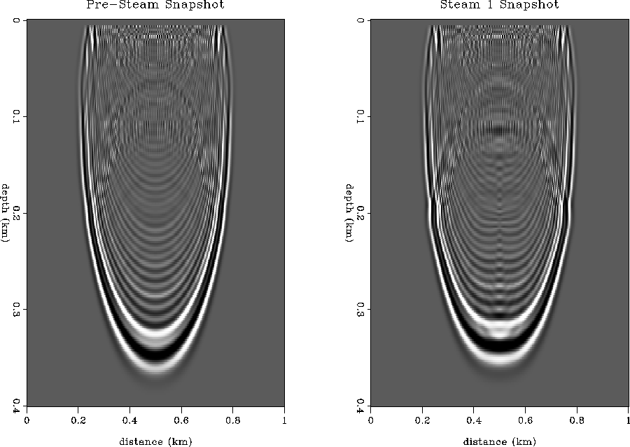
Figure ![[*]](http://sepwww.stanford.edu/latex2html/cross_ref_motif.gif) shows a snapshot of the wavefield before and after steam
injection. Note that the steam snapshot has a much larger upgoing
reflection branch, and is slightly flattened due to time delay
on the leading downgoing branch.
shows a snapshot of the wavefield before and after steam
injection. Note that the steam snapshot has a much larger upgoing
reflection branch, and is slightly flattened due to time delay
on the leading downgoing branch.
Figure ![[*]](http://sepwww.stanford.edu/latex2html/cross_ref_motif.gif) shows the shot gathers corresponding to the
two point-source shots before and after steam injection.
Note that the top of reservoir reflection at 210 ms has changed
dramatically. It is much brighter and contains a polarity reversal.
This polarity reversal occurs where the low-velocity steam zone
transitions into the high-velocity pressure front.
This polarity effect might explain the polarity reversal seen in
the field data of Figures
shows the shot gathers corresponding to the
two point-source shots before and after steam injection.
Note that the top of reservoir reflection at 210 ms has changed
dramatically. It is much brighter and contains a polarity reversal.
This polarity reversal occurs where the low-velocity steam zone
transitions into the high-velocity pressure front.
This polarity effect might explain the polarity reversal seen in
the field data of Figures ![[*]](http://sepwww.stanford.edu/latex2html/cross_ref_motif.gif) and
and ![[*]](http://sepwww.stanford.edu/latex2html/cross_ref_motif.gif) ,
and suggest that there is a pressure front in the field data.
Finally, note the diffractions from the steam zone. These also match
diffractions seen in the field data, and suggest the lateral extent
of a steam zone.
,
and suggest that there is a pressure front in the field data.
Finally, note the diffractions from the steam zone. These also match
diffractions seen in the field data, and suggest the lateral extent
of a steam zone.
Plane-wave modeling
Figure ![[*]](http://sepwww.stanford.edu/latex2html/cross_ref_motif.gif) shows a finite difference acoustic simulation of
a plane wave source leaving the surface at vertical incidence.
The snapshot shows that the plane-wave is delayed by the steam zone
in the center at the injection well, compared to the pre-steam
synthetic. Diffractions are clearly visible at the center point.
The outer limbs of the plane wave are pulled up in time, but the
effect is too small to see in a static display.
shows a finite difference acoustic simulation of
a plane wave source leaving the surface at vertical incidence.
The snapshot shows that the plane-wave is delayed by the steam zone
in the center at the injection well, compared to the pre-steam
synthetic. Diffractions are clearly visible at the center point.
The outer limbs of the plane wave are pulled up in time, but the
effect is too small to see in a static display.
Figure ![[*]](http://sepwww.stanford.edu/latex2html/cross_ref_motif.gif) shows the ``wave-stack'', Schultz and Claerbout
, that would have been recorded
at the surface for the vertically incident plane-wave source.
This wave-stack is similar to an NMO stack section, except it
makes no velocity assumption. Note the presence of a strong
diffraction associated with the steam zone. Also note the polarity
changes and zero crossing along the top reservoir reflection from
the steam zone to the high-pressure zone. The wave-stack
clearly shows velocity time sag and amplitude focusing below the steam zone,
and time pull-up at the survey edges beneath the portion of the reservoir
containing the high-pressure front. All of these effects are somewhat
visible in the field data sections of Figures
shows the ``wave-stack'', Schultz and Claerbout
, that would have been recorded
at the surface for the vertically incident plane-wave source.
This wave-stack is similar to an NMO stack section, except it
makes no velocity assumption. Note the presence of a strong
diffraction associated with the steam zone. Also note the polarity
changes and zero crossing along the top reservoir reflection from
the steam zone to the high-pressure zone. The wave-stack
clearly shows velocity time sag and amplitude focusing below the steam zone,
and time pull-up at the survey edges beneath the portion of the reservoir
containing the high-pressure front. All of these effects are somewhat
visible in the field data sections of Figures ![[*]](http://sepwww.stanford.edu/latex2html/cross_ref_motif.gif) and
and ![[*]](http://sepwww.stanford.edu/latex2html/cross_ref_motif.gif) .
.
vp123g-ann
Figure 12 Velocity profiles of reservoir
containing: heavy oil (left), steam (center), and high-pressure
dissolved gas (right).


 vp1
vp1
Figure 13 Velocity model before steam injection.
Heavy-oil reservoir is at 200 m depth.


 vp2
vp2
Figure 14 Velocity model after 5 months of steam
injection. Low velocity anomaly in the center (dark gray)
is due to steam, high velocity anomalies on the flanks (white)
are due to the high-pressure front.


 waves12
Figure 15 FD acoustic modeling wavefield snapshots:
before steam injection (left), during steam (right).


 shot12
Figure 16 FD acoustic modeled shot gathers:
before steam injection (left), during steam (right).


 pwave12
Figure 17 FD acoustic planewave snapshots (p=0):
before steam injection (left), during steam (right).


 wstk12
Figure 18 FD acoustic planewave wavestacks (p=0):
before steam injection (left), during steam (right).


DISCUSSION
In this section, I interpret the combined analysis of the steamflood
model, rock physics, seismic modeling, and field data observations.
It appears that the bright reflection disk centered on the injector well
and the time sag beneath must indicate the extent of the steam zone, not
merely hot fluid. The rock physics analysis has shown that the steam
zone should be expected to show velocity decreases of up to 30%,
whereas hot water or oil increases velocity by only 10% or less.
Finite difference modeling of a reasonable steamflood velocity model
shows strong diffractions and bright reflections emanating from the
steam zone, that can be interpreted to match similar features in the
field data. This analysis implies that the steam zone is about 25 m
in diameter
at the top of the reservoir, 50 m in diameter at the base of the reservoir,
and possibly heading west faster than east. This correlates with
core measurements that the top part of the reservoir
is at least one order of magnitude less permeable than the bottom part,
and that at 5 months of steam injection, substantial heating has
arrived at the T1 temperature monitor well to the west, but not the T2
well to the east.
My analysis suggests that the hot oil ring may be seismically
transparent, but that the hot water ring might be visible since it
causes a 10-15% velocity increase. Close inspection of the
time slice in Figure ![[*]](http://sepwww.stanford.edu/latex2html/cross_ref_motif.gif) shows a thin dark gray
ring surrounding the white steam disk. This ring is about 25 m thick
and corresponds to time pull-up (velocity increase) in the migrated
inline section of Figure
shows a thin dark gray
ring surrounding the white steam disk. This ring is about 25 m thick
and corresponds to time pull-up (velocity increase) in the migrated
inline section of Figure ![[*]](http://sepwww.stanford.edu/latex2html/cross_ref_motif.gif) . The dark gray
amplitude suggests it is opposite reflection polarity to the steam zone,
which matches the predicted hot water properties.
Perhaps this dark gray ring is the seismic view of the hot water annulus.
. The dark gray
amplitude suggests it is opposite reflection polarity to the steam zone,
which matches the predicted hot water properties.
Perhaps this dark gray ring is the seismic view of the hot water annulus.
I predict that a large area of the 7-spot pattern
should be subject to a fast-propagating high-pressure cold oil front.
This pressure front should be seismically visible since it causes a
20% increase in velocity. Finite difference modeling shows that the
high-pressure front can cause polarity reversals on seismic events
and time pull-up due to velocity increase. Figures ![[*]](http://sepwww.stanford.edu/latex2html/cross_ref_motif.gif) and
and ![[*]](http://sepwww.stanford.edu/latex2html/cross_ref_motif.gif) show these polarity effects to the south and
east of the injector, which are in the opposite direction to the fastest
heat propagation direction given by the temperature observation wells.
Perhaps the pressure front has already propagated past the edge of the
survey to the north-west, but is moving slower, and thus still visible,
to the south-east.
Below the reservoir base of 200 ms, large seismic changes
occur all the way to the edge of the 7-spot pattern. This could
coincide with the fact that the pressure front has travelled quickly
to the edges of the pattern, and effects only those reflectors
below the base of the reservoir, not within or above.
These seismic changes below the reservoir base could be caused by
time pull-up due to the pressure front velocity increase.
The dark gray reflectivity of a large outer semi-ring might be interpreted
as the pressure front in Figure
show these polarity effects to the south and
east of the injector, which are in the opposite direction to the fastest
heat propagation direction given by the temperature observation wells.
Perhaps the pressure front has already propagated past the edge of the
survey to the north-west, but is moving slower, and thus still visible,
to the south-east.
Below the reservoir base of 200 ms, large seismic changes
occur all the way to the edge of the 7-spot pattern. This could
coincide with the fact that the pressure front has travelled quickly
to the edges of the pattern, and effects only those reflectors
below the base of the reservoir, not within or above.
These seismic changes below the reservoir base could be caused by
time pull-up due to the pressure front velocity increase.
The dark gray reflectivity of a large outer semi-ring might be interpreted
as the pressure front in Figure ![[*]](http://sepwww.stanford.edu/latex2html/cross_ref_motif.gif) .
.
ONGOING WORK
I continue to work with this complex and fascinating data set.
I am working with all five 3-D seismic monitor data sets, and incorporating
well log information. I am also working to properly 3-D depth migrate
these data after depth migration velocity analysis. I may use
experience in 3-D AVO analysis to sort out
velocity versus reflectivity changes in this data, if necessary.
I hope to better understand the seismic changes from survey to survey,
and test whether the pressure front can be used as a tool to
predict future thermal fluid flow months in advance.
CONCLUSIONS
I have attempted to explain changes in seismic monitoring data sets
acquired over an active steamflood project. By combining field data
observations with a steamflood fluid-flow model, rock physics analysis
and seismic modeling, I have assembled a plausible interpretation of the
field data. A disk of steam can be seen in the seismic data that
extends to a diameter of about 50 m, surrounded by what may be a 20 m
annulus of hot water. The hot oil annulus is probably seismically transparent.
Beyond that, a fast-propagating high-pressure cold oil front causes
strong velocity increases by driving residual gas saturation above the
bubble point. The evidence for the pressure front includes polarity
reversals along the base of reservoir reflector, and wide-spread seismic
changes (velocity pull-up?) below the reservoir base out to the edges of
the survey. This high-pressure front could be a powerful tool for predicting
future oil flow months in advance of the thermal front.
[MISC,GEOTLE,SEGBKS,SEGCON,GEOPHYSICS]


![[*]](http://sepwww.stanford.edu/latex2html/prev_gr.gif)


Next: About this document ...
Up: Table of Contents
Stanford Exploration Project
5/9/2001
![[*]](http://sepwww.stanford.edu/latex2html/cross_ref_motif.gif) shows a diagram of a single ``7-spot'' steam
injection well pattern. The surface area of the 4-D seismic coverage is
outlined by the outer box, and is 355 m on a side. The 7-spot is
composed of six producing wells (black circles) connected in a hexagon,
with the seventh well being the steam injector in the center (open circle
with arrow).
Additionally, two temperature observation wells (open circles)
are located on either side of the injector.
shows a diagram of a single ``7-spot'' steam
injection well pattern. The surface area of the 4-D seismic coverage is
outlined by the outer box, and is 355 m on a side. The 7-spot is
composed of six producing wells (black circles) connected in a hexagon,
with the seventh well being the steam injector in the center (open circle
with arrow).
Additionally, two temperature observation wells (open circles)
are located on either side of the injector.
![[*]](http://sepwww.stanford.edu/latex2html/prev_gr.gif)

![[*]](http://sepwww.stanford.edu/latex2html/movie.gif)
