

![[*]](http://sepwww.stanford.edu/latex2html/prev_gr.gif)


ABSTRACTElsewhere in this report, Ji and Palacharla (1994) show the difficulty of obtaining angle-dependent reflectivities by conventional prestack methods such as profile imaging. Imaging by wavefront synthesis is a good alternative to achieve such a goal. One of the wavefront synthesis methods is controlled illumination (Rietveld and Berkhout, 1992; Berkhout, 1992). This method consists of two steps, areal shot record synthesis and areal shot record migration. Angle-dependent reflectivity images can be obtained by combining the field shot records in such a way that the related areal source wave field has a predefined shape, like a constant ray parameter or a constant incidence angle at the target depth level. I tested the algorithm with the Marmousi data. |
During the past decade, the use of AVO (amplitude versus offset) type analysis in petroleum exploration has become increasingly common (Ostrander, 1982). Even though the objective of AVO analysis is to observe angle-dependent reflectivity behavior, the name amplitude versus offset was chosen because most of the amplitude analysis is done in the common midpoint gather.
However, problems associated with AVO analysis may give false indications of hydrocarbon presence or may not be seen in the common midpoint gather because of complicated velocity and arbitrary reflector shape of the subsurface.
Knowing the incidence angle at the reflector and the corresponding reflectivity allows us to analyze the properties of a reflector more correctly. Thus, angle-dependent reflectivity analysis can provide more accurate information about the reflector.
Even though conventional prestack migration methods such as profile imaging theoretically provide a reflectivity map, it is not practically feasible (Ji and Palacharla, 1994). Imaging by wavefront synthesis is a good alternative to obtain such a goal. One of the wavefront synthesis methods is controlled illumination (Rietveld and Berkhout, 1992; Berkhout, 1992).
This paper describes the wavefront synthesis imaging methods and reports on my testing of the method, as a tool for analyzing the angle-dependent reflectivity, with the Marmousi data.
CONTROLLED ILLUMINATION
Controlled illumination is a target-oriented imaging technique. If the wavefield has a predefined shape at the target reflector, the image obtained from such a wavefield is easier to interpret in terms of angle-dependent reflection coefficient at the target reflector because we know the incidence angle of the wavefront.
Controlled illumination consists of two steps: areal shot record synthesis, and areal shot record migration. The areal shot record is generated by combining field shot records so that the related areal source wave field has a predefined shape at the target level. Migration of these target-oriented areal shot record is done by conventional shot profile migration.
Synthesis of areal shot records
Huygens' principle permits the synthesis of arbitrarily shaped downward propagating wavefronts from the superposition of many spherical wavefronts. In other words, we can synthesize an arbitrarily shaped wavefront in a predefined way by superposition of many shot records (Schultz and Claerbout, 1978; Berkhout, 1992).
Suppose that we want to have a downgoing wavefield
![]() at depth zn.
Such a wavefield can be obtained by propagating
a certain wavefield at the surface,
at depth zn.
Such a wavefield can be obtained by propagating
a certain wavefield at the surface, ![]() ,to the depth level zn, as follows:
,to the depth level zn, as follows:
| (1) |
| (2) |
| (3) |
If we assume that each shot gather, U(w,x,z0|xs), is caused by an impulse at xs, the response of the areal shot can be synthesized using the superposition formula
| (4) |
Imaging of areal shot records
The imaging is performed in the same manner as a profile imaging
scheme (Claerbout, 1985) with ![]() as the upcoming wave and
as the upcoming wave and
![]() as the downgoing wave.
as the downgoing wave.
For each depth level, extrapolation is performed as follows:
![]()
![]()
If we remember that the upcoming wavefield is the convolution
of the reflectivity with the downgoing wave field,
the reflection coefficient can be obtained
from Equations (1) and (2) by deconvolving ![]() from
from
![]() as follows:
as follows:
| (5) |
Example
In the SEP-79 (Ji, 1993), I tested this algorithm with the Marmousi data, but couldn't get the image in the deeper portion of the Marmousi model. The problem may have been the poor extrapolation operator. To calculate the propagation operator, W(zn,z0), I used the Split-step Fourier method (Stoffa et al, 1990), which I have found that it does not handle the wavefield correctly in the case of very rapid change in lateral velocity.
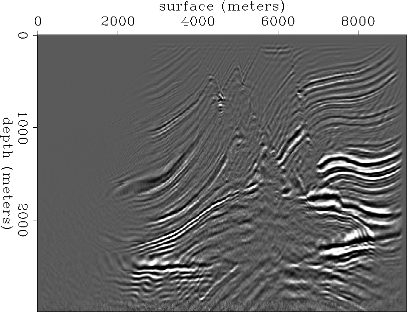
For this paper, I have chosen the finite-difference method for the extrapolation with optimized coefficients (Lee and Suh, 1986) and can obtain the images in the deep portion of the Marmousi model. The resulting migrated image using finite-difference operator is shown in Figure conill-stk. To obtain it I stacked ten images that were generated by simulating planewaves at ten different depth levels with several different incidence angles. The Figure shows the image of the deeper portion, which is the target in the Marmousi data.
 |
ANGLE-DEPENDENT REFLECTIVITY In order to retrieve the angle-dependent reflectivity, we need to know the incidence angle of the planewave along the reflector. Since the correct incidence angle requires the reflector's geometry, which is often not available in the real data, illuminating wavefronts at every depth level with a constant incidence angle or a constant ray parameter may help to reveal the pseudo angle-dependent reflectivity image.
Constant ray parameter at each depth If the reflector in the subsurface is generally gentle and the lateral velocity change is small, a slanted wavefront with a constant ray parameter would be enough to retrieve the angle-dependent reflectivity.
In order to synthesize an areal shot record
for a slanted wavefront with a constant-ray parameter at a depth level,
the impulse in each trace of the predefined wave field,
![]() , must have time lag,
, must have time lag, ![]() ,with respect to every other trace.
If the trace interval is
,with respect to every other trace.
If the trace interval is ![]() , then
, then
| (6) |
 |
Constant incidence angle at each depth Even though the reflector in the subsurface is generally gentle, if the lateral velocity change is not small, a slanted wavefront with a constant ray parameter may not be enough to retrieve the angle-dependent reflectivity. We then need to have a slanted wavefront with a constant-incidence angle.
In order to synthesize an areal shot record
for a slanted wavefront with a constant-incidence angle at a depth level,
the impulse in each trace of the predefined wavefield,
![]() , must have time lag,
, must have time lag, ![]() ,with respect to every other trace.
If the trace interval is
,with respect to every other trace.
If the trace interval is ![]() , then
, then
| (7) |
| (8) |
| (9) |
anglesignheight=2.5in,width=5.in The sign convention for the slanted plane wavefront.
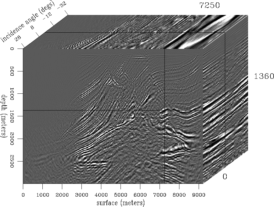
Figure conill-ang shows the result of the constant incidence angle illumination with the Marmousi data. To save computing time, the wavefronts were simulated only at 37 depth levels to have a constant incidence-angle and the images around the simulated depth were windowed and patched together to produce a constant incidence angle image. This imaging was iterated for various angles from 30 degrees to -30 degrees.
 |
It is not easy to obtain angle-dependent reflectivities by conventional prestack imaging like profile imaging (Ji and Palacharla, 1994). Imaging by wavefront synthesis is a good alternative to achieve such a goal. The controlled illumination method was tested to recover the angle-dependent reflectivities for the Marmousi data. Angle-dependent reflectivity images can be obtained by combining the field shot records in such a way that the related areal source wave field has a predefined shape, like a constant ray parameter or a constant incidence angle at the target depth level. The testing with the Marmousi dataset showed a limited success. Most of images obtained by different illumination angles and ray parameters are lined up very well. But the amplitude behavior along the angles and ray parameters are not consistent. This might be due to the irregularity of the reflectors and the strong lateral velocity change because such situations make the assumption of the constant angle or ray parameter not valid after a few more depth extrapolation steps.
In order to attack this problem further, I plan to apply a slanted wavefront with a constant incidence-angle along the irregular reflectors. Since the reflectivity obtained by this approach is valid along the predefined reflector, I expect the more reasonable reflectivity behavior with respect to the incidence angle.