![[*]](http://sepwww.stanford.edu/latex2html/prev_gr.gif)


Next: About this document ...
Up: Table of Contents
Seismic monitoring of oil production:
A feasibility study
D. Lumley![[*]](http://sepwww.stanford.edu/latex2html/foot_motif.gif) ,
A. Nur,
S. Strandenes,
J. Dvorkin,
J. Packwood
,
A. Nur,
S. Strandenes,
J. Dvorkin,
J. Packwood
Author has no known email address
ABSTRACT
We perform a feasibility study on the likelihood of seismically
detecting and interpreting the time-varying changes in a North Sea reservoir
during solution-gas-drive oil production from a horizontal well.
This study integrates reservoir engineering fluid-flow simulations,
rock physics measurements and transformations,
and prestack seismic modeling and migration on a real but anonymous
North Sea reservoir model.
We calculate spatial distributions of reservoir rock properties from the
fluid-flow simulation data, and map the associated
seismic responses at three production-time snapshots:
prior to any oil production (Base Survey), after 56 days (Monitor 1),
and after 113 days (Monitor 2) of oil production.
Multi-offset seismic surveys are simulated for each of these
three production times. Using realistic seismic acquisition
parameters, we are able to successfully
detect and monitor dynamic gascap expansion in the reservoir
during the fluid-flow simulation of the oil production process.
Evidence of gas coning is clearly visible in the
prestack-migrated difference sections at realistic seismic
noise levels and frequency bandwidth.
|
INTRODUCTION
Hydrocarbon reservoirs are increasingly recognized as spatially heterogeneous
entities in terms of pore-fluid content, pore-fluid saturation, porosity,
permeability, lithology, and structural control. Knowledge of these reservoir
parameters and their spatial variation is critical in the evaluation of the
total volume of hydrocarbon reserves in place, in understanding and predicting
physical processes in the reservoir such as fluid flow and heat transfer,
and in projecting and monitoring reservoir fluid production and recovery
as a function of time.
A new diagnostic role for seismic has recently been proposed,
in which several repeat seismic surveys are acquired in time-lapse mode
to monitor reservoir production fluid-flow processes (e.g., Nur, 1989).
This concept offers a
method for better characterization of reservoir complexity by monitoring
the flow of fluids with time in a producing reservoir.
Additionally, 3-D seismic monitoring may provide a full reservoir volume
analysis of production sweep efficiency, early breakthrough prediction,
and location of bypassed (unproduced) hydrocarbons.
Seismic monitoring of reservoir production processes potentially
offers a new dimension to the manner in which hydrocarbon reservoirs
are currently developed and produced.
Previous work
Although the concept of time-lapse seismic reservoir monitoring
is relatively recent, a few notable pilot projects have been attempted.
Pullin et al. (1987) collected two 3-D seismic surveys before and after a
steam pilot at an Athabasca tar sands reservoir site. By comparing time
delay and amplitude attenuation maps between the two stacked surveys,
they seemed to be able to qualitatively map the location of
heated versus unheated zones. Their observed vertical time delays
and amplitude attenuations through heated sections of the reservoir
compared reasonable well with prior rock physics laboratory studies
of the predicted thermal effects on seismic data.
Eastwood et al. (1994) performed a similar analysis
on a 3-D seismic monitor of an Alberta cyclic steam stimulation.
Greaves and Fulp (1987) designed and analyzed a 3-D seismic
monitoring experiment of an in situ combustion (fireflood)
enhanced oil recovery (EOR) process.
They collected three 3-D surface seismic datasets: one before combustion,
and two during combustion. They made stacked sections from each survey
and computed traveltime and amplitude difference maps comparing each
fireflood data set to the pre-fire base survey. They were able to monitor
the volume of combustion burn accurately, as well as the sweep efficiency,
with confirmation by pre- and post-burn borehole measurements.
More recently, Graebner (1993) presented results of a 3-D marine seismic
monitoring survey in the Oseberg field offshore Norway.
The objective was to monitor the movement of the gascap over time
during production. They compared reservoir fluid-flow simulation predictions
of the gas-oil contact movement to the actual seismic observations,
and found a weak seismic amplitude anomaly that partially correlated
with the fluid-flow simulation data.
They state that their results were inconclusive due to significant noise
in the final seismic difference sections, and concerns about
calibrating relative and absolute positioning errors between surveys.
Current research
In this paper,
we present what we believe to be a major step forward in establishing
the petrophysical basis for seismic reservoir monitoring, by
conducting a comprehensive physical modeling study that integrates
fluid-flow simulation and rock physics with seismic modeling and
migration. We demonstrate the potential feasibility of performing seismic
reservoir monitoring with a North Sea reservoir case study.
Fluid-flow simulations were computed by Norsk Hydro for the case
of solution-gas-drive oil production from a horizontal well in the
reservoir after 56 and 113 days of production. Reservoir geology
and core data measurements were combined to make rock physics
transformations of the fluid-flow saturation, pressure and temperature data
to seismic velocities and densities. Multi-offset elastic reflection
seismogram surveys were simulated at each production phase.
Prestack migration images clearly show gas coning during production
for reasonable seismic noise levels and frequency bandwidth.
Our feasibility study may help reduce the financial risk
associated with designing and implementing a seismic monitoring project
given a pre-monitor engineering and petrophysical reservoir database.
FLUID-FLOW SIMULATION
The reservoir in this study is located within a large oil and gas field
in the North Sea. The oil zone is at a depth of approximately 1500 meters,
and it varies in thickness from a few meters to more than 20 meters.
Horizontal drilling technology makes it possible to commercially produce oil
from this thin oil zone. A horizontal well penetrates this oil zone
in the center of the simulation grid, and is perforated along the borehole
for a length of a few hundred meters.
Norsk Hydro provided fluid-flow simulations of primary oil production from
a horizontal well in the reservoir.
The timeframe of the two simulation datasets was 56 and 113 days into
production.
Reservoir properties
The productive interval of the reservoir consists of loosely consolidated
sands with porosities ranging from 23% to 35%.
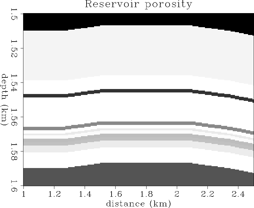
Figure ![[*]](http://sepwww.stanford.edu/latex2html/cross_ref_motif.gif) shows the distribution of porosity in the
reservoir on the simulation grid.
All three fluid phases of gas, oil and water are simultaneously present.
The reservoir oil is fairly heavy with a low gas-to-oil ratio of about 60.
Typical values for the oil at reservoir conditions are: density 0.8 g/cc,
bulk modulus 1020 MPa, viscosity 1.5 to 2.0 cp.
The temperature in the reservoir is approximately
uniform and constant at 60 C. The overburden pressure is
approximately 34 MPa and the pore pressure is about 16 MPa.
shows the distribution of porosity in the
reservoir on the simulation grid.
All three fluid phases of gas, oil and water are simultaneously present.
The reservoir oil is fairly heavy with a low gas-to-oil ratio of about 60.
Typical values for the oil at reservoir conditions are: density 0.8 g/cc,
bulk modulus 1020 MPa, viscosity 1.5 to 2.0 cp.
The temperature in the reservoir is approximately
uniform and constant at 60 C. The overburden pressure is
approximately 34 MPa and the pore pressure is about 16 MPa.
phi
Figure 1 Porosity distribution in the reservoir,
ranging from 23% (black) to 35% (white).
Simulation grid
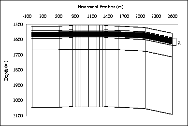
The reservoir grid consists of 312 individual blocks, as
schematically diagrammed in Figure .
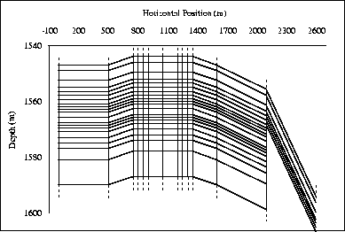
Figure shows an expanded section of the
reservoir grid in zone A.
This irregular simulation grid ranges in depth intervals of one to tens
of meters, and lateral intervals of tens to hundreds of meters.
The grid covers a reservoir zone 45 m thick, comprised of 24 layers.
The maximum structural dip along the reservoir is about 6
at the right end which is truncated by 40 m of fault throw.
At both production times of 56 and 113 days, each grid cell was
provided with a fluid-flow simulation data value of
pore pressure, gas saturation, oil saturation, and water saturation.
Temperature remained constant throughout the simulation.
res-grid1
Figure 2 The reservoir fluid-flow simulation grid.
Grid coordinates are shifted 750 m laterally compared to physical
coordinates.
res-grid2
Figure 3 An expanded section ``A'' of the reservoir
fluid-flow simulation grid.
Grid coordinates are shifted 750 m laterally compared to physical
coordinates.
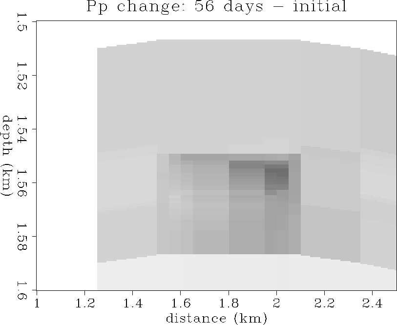
Pore pressure
Pore pressure was calculated in the fluid-flow simulations
for 56 and 113 days (Monitors 1 and 2) of solution-gas-drive oil
production from the horizontal well, and at the initial Base survey state.
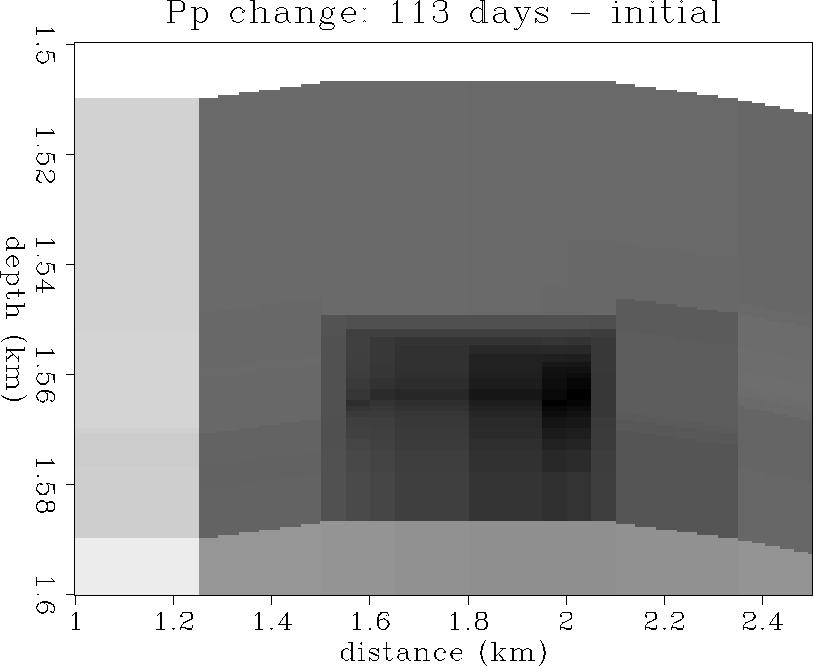
The largest change in pore pressure during 113 days of simulated
production is only -0.24 MPa (-35 psi), which is negligible in terms
of velocity effect as shown in Figure .
Figures and
show the changes in reservoir pressure of the Monitor 1 and 2
simulations compared to the initial reservoir conditions.
The diffusive decrease in reservoir pressure is associated with
the withdrawal of oil from the vicinity of the horizontal wellbore,
which is located at about 1560 m depth, and between 1.5-2.0 km distance
in the coordinates of Figure .
The well is perforated with increased density to the right, which
explains the asymmetry of the pressure decrease during drawdown.
pp21
Figure 4 Pore pressure difference:
56 days - initial state. All pressure changes are negative.
The maximum change is about -0.16 MPa (dark gray).
pp31
Figure 5 Pore pressure difference:
113 days - initial state. All pressure changes are negative.
The maximum change is about -0.24 MPa (black).
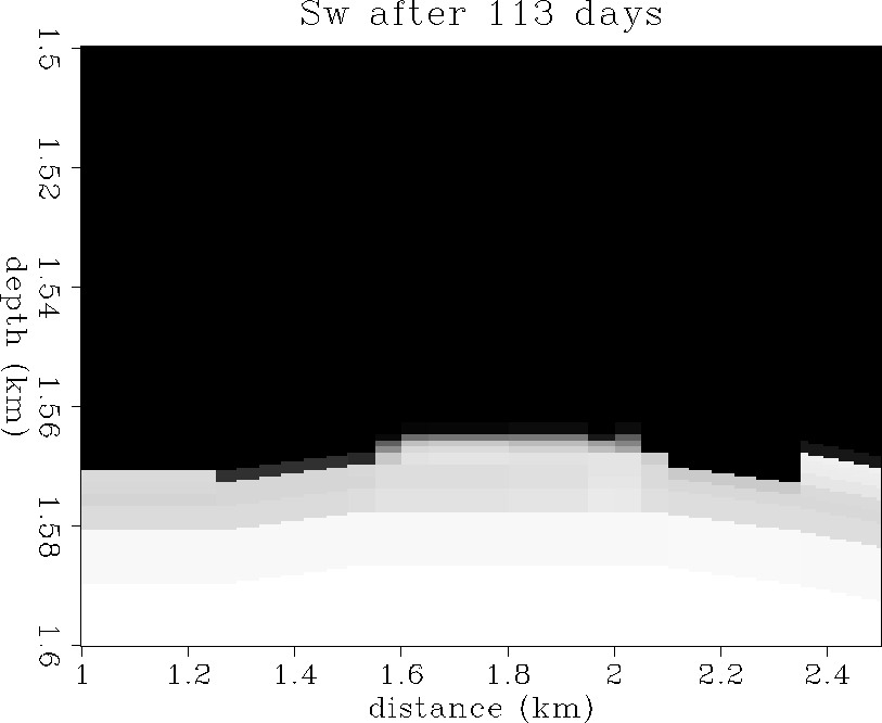
Oil saturation
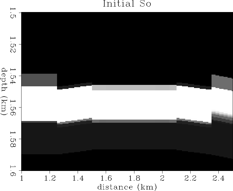
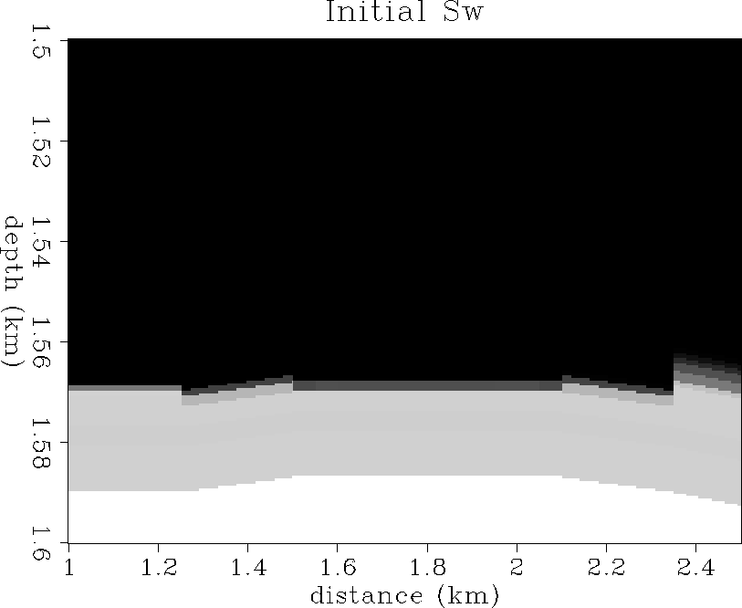
Figure shows the initial oil saturation state
in the reservoir. The main oil zone is about 20 m thick at
a depth of 1550 m and has a maximum saturation value of 90%.
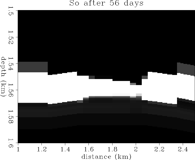
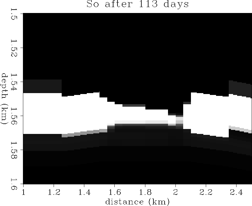
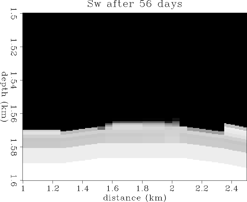
Figures and show the oil saturation
distribution after 56 and 113 days of solution-gas drive respectively.
These plots show the oil zone being pinched out rapidly by
gascap expansion from above, and aquifer upwelling from below.
This is usually indicative that the production rate is too fast
to maintain a stable oil zone.
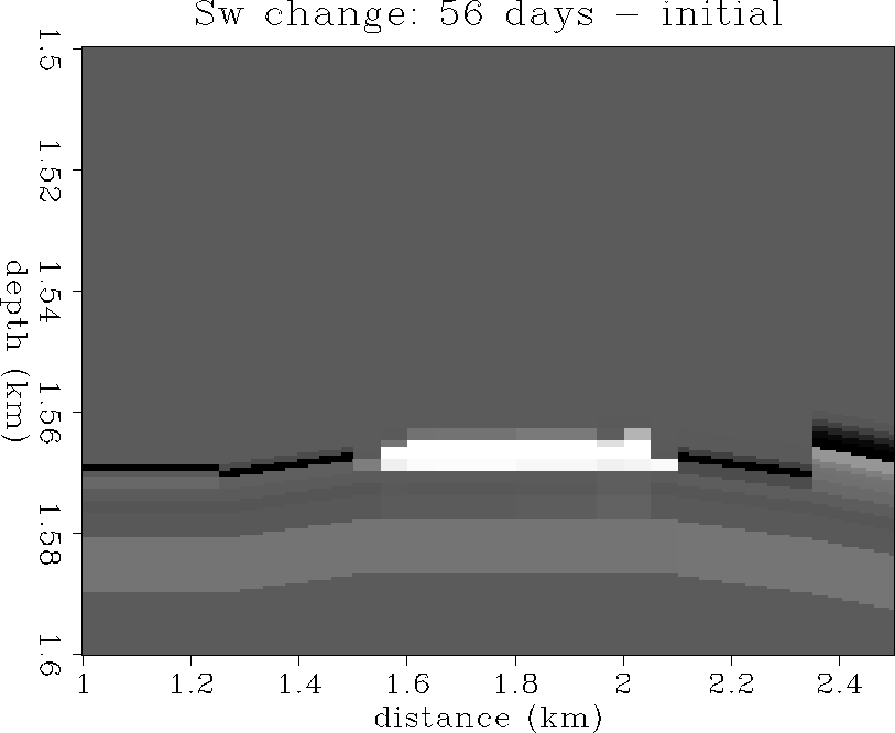
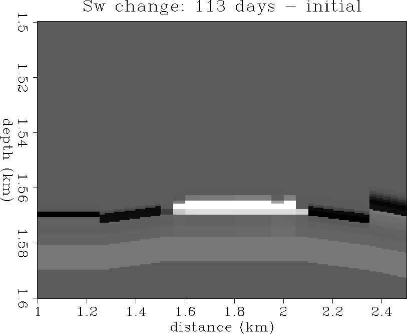
Figures and show the changes in oil saturation
from the initial state to 56 and 113 days of production.
The pinchout due to gascap expansion and aquifer coning is clearly evident,
as well as a slight overall downward migration of the entire oil zone
due to the gas expanding above.
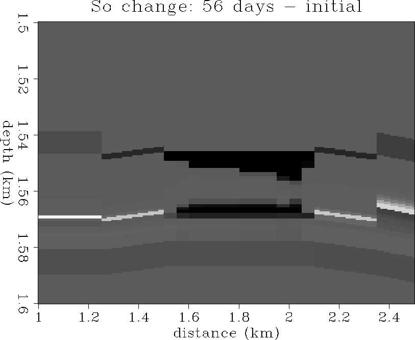
so1
Figure 6 The initial oil saturation distribution.
100% saturation is white, 0% saturation is black.
so2
Figure 7 The oil saturation distribution after
56 days of production.
100% saturation is white, 0% saturation is black.
so3
Figure 8 The oil saturation distribution after
56 days of production.
100% saturation is white, 0% saturation is black.
so21
Figure 9 The change in oil saturation:
56 days - initial state.
+100% is white, -100% is black.
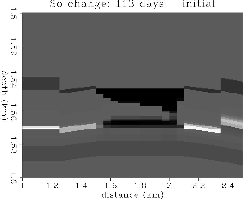
so31
Figure 10 The change in oil saturation:
113 days - initial state.
+100% is white, -100% is black.
Water saturation
Figure shows the initial water saturation state
in the reservoir. A large aquifer underlays the oil zone,
and the oil-water contact follows reservoir structure and porosity
rather than a gravity fluid contact.
Figures and show the water saturation
distribution after 56 and 113 days of solution-gas drive respectively.
Note the aquifer coning upward in the center and the gravity sag
at the flanks of the aquifer cone.
Figures and show the changes in water saturation
from the initial state to 56 and 113 days of production.
The aquifer has coned upward near the horizontal wellbore
to displace oil into production. Gravitational forces cause
a slight downwelling of the aquifer at the flanks to balance the
upward coning in the center.
sw1
Figure 11 The initial water saturation distribution.
100% saturation is white, 0% saturation is black.
sw2
Figure 12 The water saturation distribution after
56 days of production.
100% saturation is white, 0% saturation is black.
sw3
Figure 13 The water saturation distribution after
113 days of production.
100% saturation is white, 0% saturation is black.
sw21
Figure 14 The change in water saturation:
56 days - initial state.
+100% is white, -100% is black.
sw31
Figure 15 The change in water saturation:
113 days - initial state.
+100% is white, -100% is black.
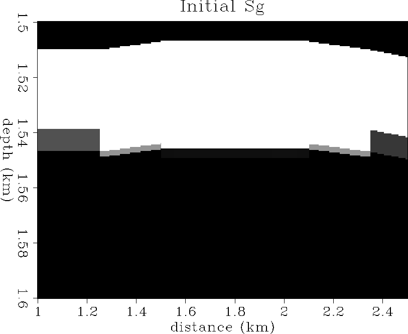
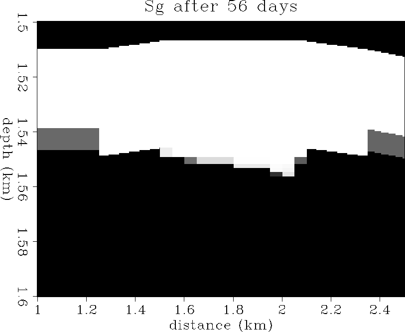
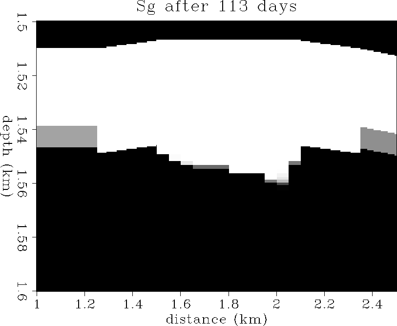
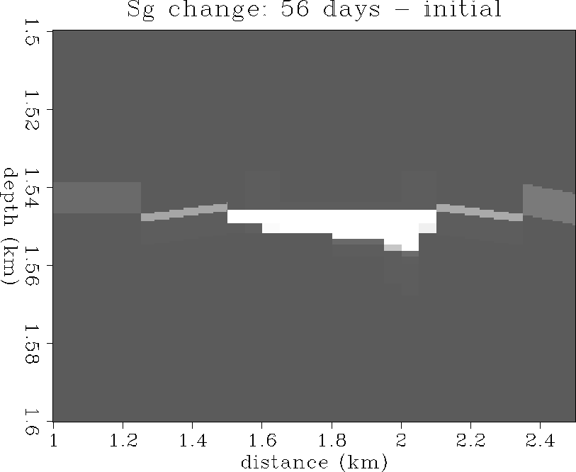
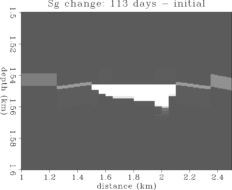
Gas saturation
Figure shows the initial gas saturation state
in the reservoir. A 50 m thick gascap overlays the oil zone,
and is sealed at the top by an impermeable cap rock.
Figures and show the gas saturation
distribution after 56 and 113 days of solution-gas drive respectively.
Note the gascap coning downward in the center due to gas expansion
associated with the reservoir pressure decrease.
Figures and show the changes in gas saturation
from the initial state to 56 and 113 days of production.
The gascap has coned downward near the horizontal wellbore
to displace oil into production. Since the compressibility of
gas is orders of magnitude larger than that of water, the gascap
cones downward more than the aquifer cones upward. The large gascap
expansion is the primary production mechanism for solution-gas drive.
Since a large P-impedance contrast is associated with the gas
zone, we expect to see a seismic response to the gascap coning,
as demonstrated later in this paper.
sg1
Figure 16 The initial gas saturation distribution.
100% saturation is white, 0% saturation is black.
sg2
Figure 17 The gas saturation distribution after
56 days of production.
100% saturation is white, 0% saturation is black.
sg3
Figure 18 The gas saturation distribution after
113 days of production.
100% saturation is white, 0% saturation is black.
sg21
Figure 19 The change in gas saturation:
56 days - initial state.
+100% is white, -100% is black.
sg31
Figure 20 The change in gas saturation:
113 days - initial state.
+100% is white, -100% is black.
ROCK PHYSICS
Given the fluid-flow simulation data and reservoir geology, we use
rock physics analysis to transform pressure, temperature and saturation
data into P- and S-wave velocity (Vp, Vs),
and density distributions within the reservoir.
First, the dry rock properties are estimated from laboratory core sample
measurements as a function of mineralogy, porosity, pressure and temperature.
Then, effective bulk moduli are computed for three-phase fluid mixtures of
oil, gas and water, including the effects of temperature and pressure.
Finally, saturated rock properties are calculated using Gassmann's equation
to combine the dry-rock data and effective fluid moduli as a function
of pressure, temperature, porosity, and fluid saturation.
Dry rock properties
Porosity effect
Our estimates of dry rock properties in the reservoir are based on the
results in a similar reservoir reported by Blangy and Strandenes (1991)
and Blangy (1992), which involved laboratory experiments conducted on 38
core samples. In the reservoir sand, quartz is the
dominant constituent, with volumetric content between 50% and 80%,
feldspar content is almost constant at 20%, and mica volumetric content
varies between 0% and 25%.
Ultrasonic compressional and shear wave velocities were measured at
varying differential hydrostatic stress from 5 to 30 MPa.
Overburden pressure is approximately 34 MPa and pore pressure varies
close to 16 MPa with differential pressure close to 18 MPa.
Thus we have chosen to rely on the core lab data set measured at
a differential pressure of 20 MPa.
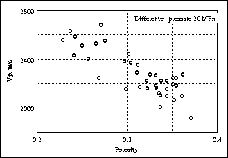
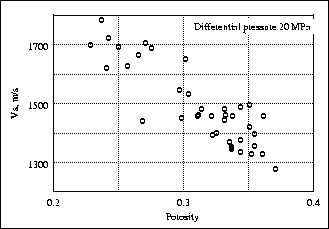
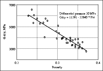
Figure shows a scatter plot of the Blangy and Strandenes
Vp core measurements made as a function of reservoir sand porosity
at 20 MPa differential pressure. Figure shows a similar scatter
plot for Vs for varying porosities at 20 MPa differential pressure.
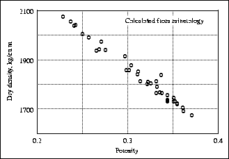
We have computed the densities of the core samples based on their
reported mineralogy volume fractions. Our dry density values are
plotted in Figure at reservoir conditions.
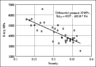
Based on the dry Vp, Vs and density data, we calculated the dry
bulk moduli Kdry and dry shear moduli Gdry of the 38 core samples
using the relation:
|  |
(1) |
where  is the dry density.
The results of the Kdry and Gdry calculations are shown
in Figures and .
We did a least-squares linear fit to the data and found:
is the dry density.
The results of the Kdry and Gdry calculations are shown
in Figures and .
We did a least-squares linear fit to the data and found:
|  |
(2) |
and
|  |
(3) |
where  is porosity on a scale of 0.0-1.0.
The standard deviation of the relative errors for each fit is
about 10% for Kdry and 5% for Gdry.
is porosity on a scale of 0.0-1.0.
The standard deviation of the relative errors for each fit is
about 10% for Kdry and 5% for Gdry.
vp-phi
Figure 21 Dry Vp measured versus porosity at 20 MPa
differential pressure (after Blangy and Strandenes).
vs-phi
Figure 22 Dry Vs measured versus porosity at 20 MPa
differential pressure (after Blangy and Strandenes).
rho-phi
Figure 23 Dry density versus porosity calculated from
mineralogy at reservoir conditions.
kdry-phi
Figure 24 Dry bulk modulus Kdry calculated
versus porosity at 20 MPa differential pressure.
gdry-phi
Figure 25 Dry shear modulus Gdry calculated
versus porosity at 20 MPa differential pressure.
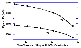
Pressure effect
Additionally, we need need to know the properties of dry rocks
with changing pore pressure. We considered measurements by Han (1986)
on unconsolidated Ottawa sand (porosity 33%) that is structurally similar
to many North Sea reservoir rocks. Han measured dry Vp and Vs as a function
of confining hydrostatic stress, which we converted into
velocity as a function of pore pressure, as shown in Figure .
A similar plot shows the variation in velocity with temperature,
but we omit this since our reservoir under study does not change
temperature during the simulated oil production.
vpvs-pp
Figure 26 Compressional and shear wave velocities
in dry Ottawa sandstone versus pore pressure at 51 MPa overburden
pressure (after Han, 1986).
Saturated rock properties
The velocity effect of saturation can be calculated at seismic frequencies
by using Gassmann's formulas (e.g., Bourbié et al., 1987).
This formula relates the effective elastic moduli of a dry rock to the
effective moduli of the same rock containing fluid:
|  |
(4) |
and
|  |
(5) |
where Ksat and Gsat are the effective bulk and shear moduli
of the saturated rock.
Gassmann's relations require knowledge of the
effective shear and bulk moduli of the dry rock (Gdry and Kdry),
the bulk modulus of the mineral material making up the rock (Ksolid),
the effective bulk modulus of the saturating pore fluid (Kfluid),
and the porosity . From Gassmann's formula we derive
|  |
(6) |
and use this last expression to compute the bulk modulus of saturated
rock from dry data.
For partially saturated rocks at sufficiently low frequencies, we use an
effective modulus Kfluid for the pore fluid that is an isostress average
of the moduli of the liquid and gaseous phases:
| 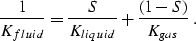 |
(7) |
This requires knowledge of the
bulk modulus of the liquid phase (Kliquid),
the bulk modulus of the gas phase (Kgas), and
the saturation values (S). In general, if the pore fluid includes more than
two phases, we calculate the mixture's effective bulk modulus Kfluid
based on the the number of fluid components N,
the volumetric concentrations ci of the ith component,
and their bulk moduli Ki:
| 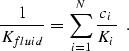 |
(8) |
Finally, we use the following formulas to find seismic velocities
in saturated rocks:
| 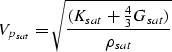 |
(9) |
and
| 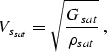 |
(10) |
where  is the density of the saturated rock:
|  |
(11) |
 is the density of the solid phase, and
 is the density of the fluid mixture obtained as an
arithmetic mean of the volume-concentration-weighted fluid density
components
is the density of the fluid mixture obtained as an
arithmetic mean of the volume-concentration-weighted fluid density
components  :
:
|  |
(12) |
We assume the following typical values for the reservoir water:
a density of 1.0 g/cc and a bulk modulus of 2250 MPa.
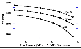
This process allows us to calculate fluid properties that depend on fluid-flow
saturation values. These properties will depend on pressure and temperature
because the bulk modulus and density of the reservoir gas are affected by
these two parameters. As an example, we convert the pressure-dependent
Ottawa sand compressional velocity of Figure to be dependent on
both pressure and fluid saturation (oil, water or gas), as shown in
Figure .
vp-pp-sat
Figure 27 Compressional velocity in Ottawa sand
as a function of pore pressure and (oil,water,gas) saturation.
Pressure-dependent gas properties
We calculate pressure- and temperature-dependent gas properties as in
Batzle and Wang (1992), and assume that the reservoir gas is primarily
methane with a specific gravity 0.55.
Pseudo-reduced pressure and temperature are related to reservoir
pore pressure and temperature as:
|  |
(13) |
and
|  |
(14) |
where G is the gas specific gravity, Ta is absolute temperature:
 . The pressure is given in MPa.
Gas density is
. The pressure is given in MPa.
Gas density is
|  |
(15) |
where the ``Z-factor'' is defined as:
| ![\begin{displaymath}
Z = [0.03 + 0.00527(3.5-T_{pr})^3]\;P_{pr}+
(0.642\;T_{pr}- 0.007\;T_{pr}^4 - 0.52) + E \;,\end{displaymath}](img24.gif) |
(16) |
and
|  |
(17) |
| ![\begin{displaymath}
\alpha = [0.45+8(0.56-T_{pr}^{-1})^2]\;P_{pr}^{1.2}\;T_{pr}^{-1}\end{displaymath}](img26.gif) |
(18) |
and R=8.31 is the universal gas constant.
The adiabatic gas bulk modulus Ks is:
| 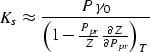 |
(19) |
where
|  |
(20) |
and  can be calculated from Equation 16 for Z.
This rock physics analysis
allows us to calculate seismic velocities in saturated reservoir rock
as a function of mineralogy, fluid type and saturation value, pore pressure
and temperature. Therefore, we can map P-wave and S-wave velocity and
density as a function of the reservoir grid directly from the
fluid-flow simulation values of pressure, temperature, and oil, gas and
water saturation.
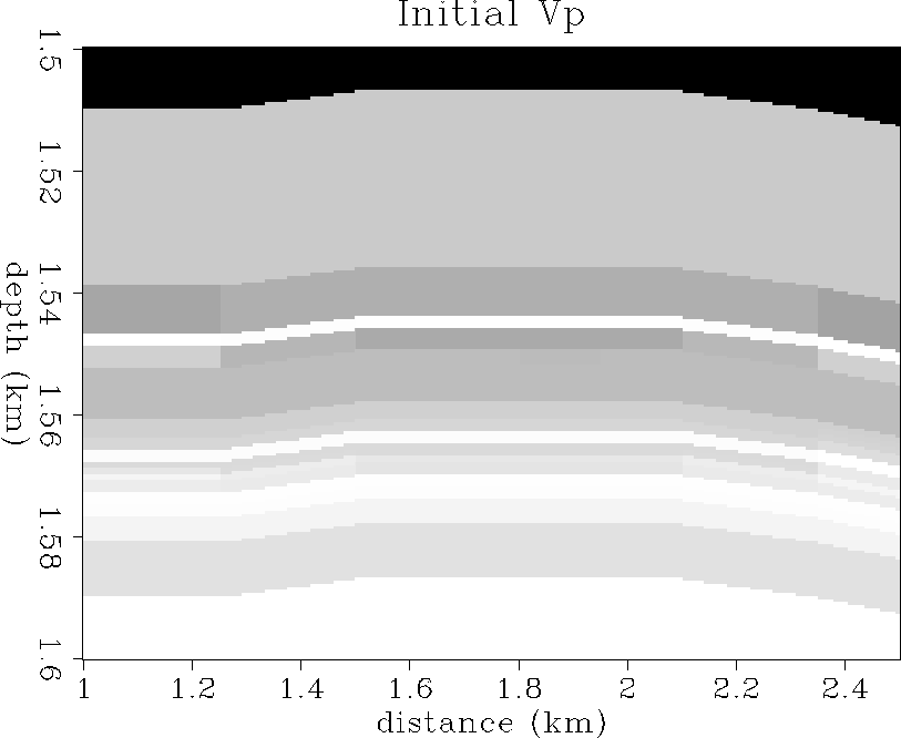
P-wave velocity
Figure shows the initial Vp velocity distribution,
which is largely controlled by the porosity at this state.
Velocities range from 2.1 km/s (dark gray) to 3.3 km/s (white).
Figures and show the Vp distribution after
56 and 113 days of oil production. A Vp decrease from about
2.5 to 2.1 km/s is evident in the area that the gascap is
expanding downward, which is due largely to gas replacing oil
in the pore space.
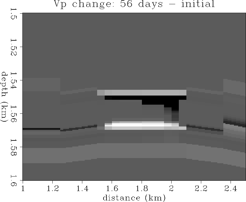
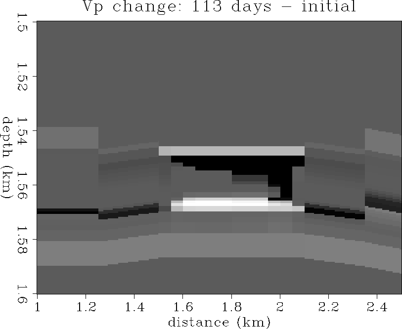
Figures and show the changes in Vp after
56 and 113 days of production. There is a -400 m/s decrease in Vp
in the gas cone, and a smaller +100 m/s increase in Vp where the
aquifer has coned upward from below allowing water to displace oil.
Density variations in the reservoir are of the same polarity as
the Vp variations. Density decreases from about 2.1 g/cc to 1.8 g/cc
in the gas cone, and increases to about 2.15 g/cc in the water cone.
Because these plots look qualitatively similar to the Vp plots,
they have been omitted here for brevity.
vp1
Figure 28 The initial Vp distribution.
Velocities range from 2.1 km/s (dark gray) to 3.3 km/s (white).
vp2
Figure 29 The Vp distribution after
56 days of production.
Velocities range from 2.1 km/s (dark gray) to 3.3 km/s (white).
vp3
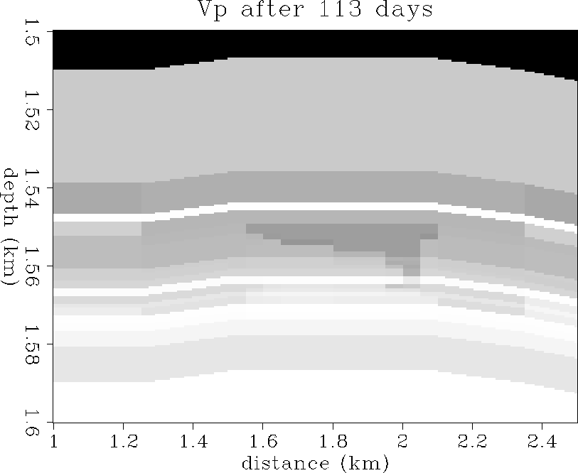
Figure 30 The Vp distribution after
56 days of production.
Velocities range from 2.1 km/s (dark gray) to 3.3 km/s (white).
vp21
Figure 31 The change in Vp:
56 days - initial state.
+140 m/s is white, -400 m/s is black.
vp31
Figure 32 The change in Vp:
113 days - initial state.
+140 m/s is white, -400 m/s is black.
S-wave velocity
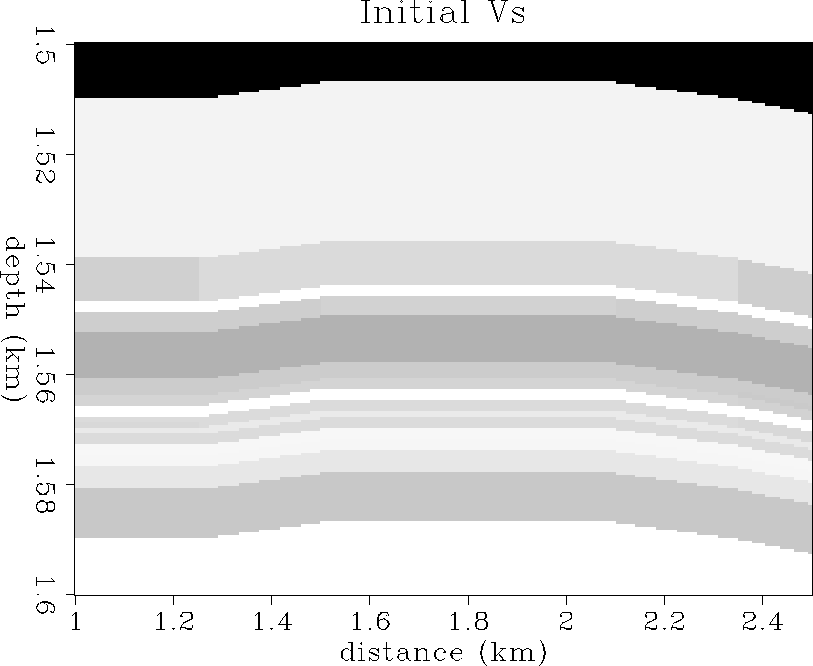
Figure shows the initial Vs velocity distribution,
which is mostly due to porosity variations.
Velocities range from 1.2 km/s (dark gray) to 2.0 km/s (white).
Figures and show the Vs distribution after
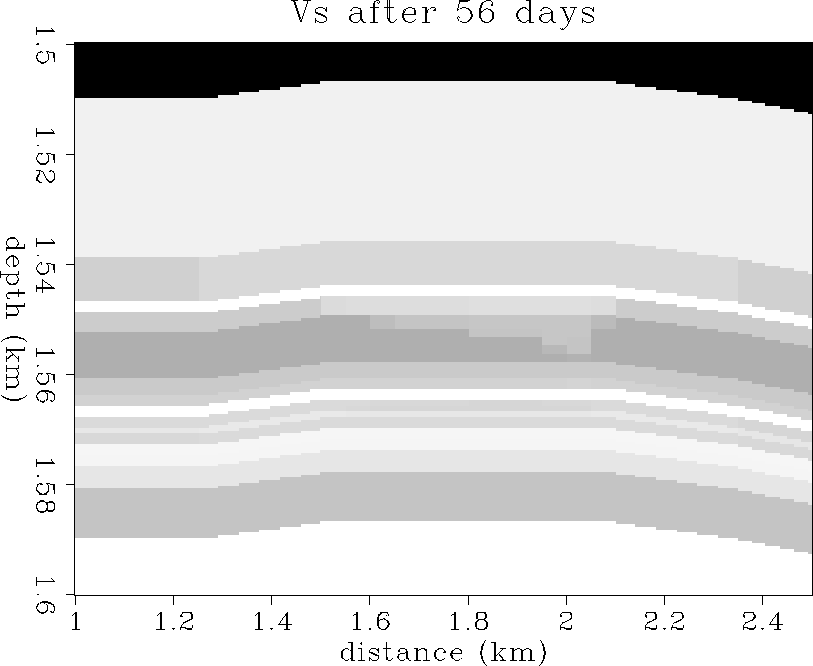
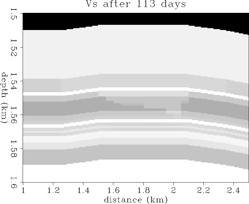
56 and 113 days of oil production. A Vs increase from about
1.5 to 1.6 km/s is evident in the area that the gascap is
expanding downward, which is due to the density decrease of gas
replacing oil in the pore space. Since the pore pressure change is too
small to affect Gdry much, and fluid saturation does not affect
the shear modulus at all according to Gassmann's equations 5,
the decrease in density due to gas replacing oil must therefore increase Vs.
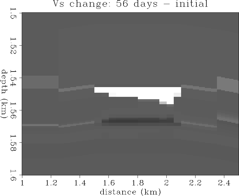
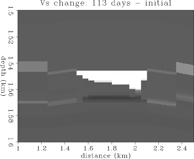
Figures and show the changes in Vs after
56 and 113 days of production. There is a +80 m/s increase in Vs
in the gas cone, and a smaller -20 m/s decrease in Vs where the
aquifer has coned upward from below allowing water to displace oil.
vs1
Figure 33 The initial Vs distribution.
Velocities range from 1.2 km/s (dark gray) to 2.0 km/s (white).
vs2
Figure 34 The Vs distribution after
56 days of production.
Velocities range from 1.2 km/s (dark gray) to 2.0 km/s (white).
vs3
Figure 35 The Vs distribution after
56 days of production.
Velocities range from 1.2 km/s (dark gray) to 2.0 km/s (white).
vs21
Figure 36 The change in Vs:
56 days - initial state.
+80 m/s is white, -20 m/s is black.
vs31
Figure 37 The change in Vs:
113 days - initial state.
+80 m/s is white, -20 m/s is black.
SEISMIC MONITORING ANALYSIS
This section of the paper deals with the seismic monitoring
analysis of the North Sea reservoir in simulated production.
In particular, we discuss the global seismic model construction, and
upscaling of fine-scale reservoir properties to an equivalent
seismic-scale reservoir model for seismogram calculation.
We used a Kirchhoff reflectivity method to simulate a prestack
surface seismic survey at each of three separate monitoring phases of
production. These three prestack datasets were then processed in
a conventional manner to produce stacked and prestack-migrated
reflectivity images. Difference images obtained by subtracting
combinations of stacked and migrated sections clearly show
that reservoir fluid production is visible in the seismic data and can be
monitored in the presence of reasonable levels of seismic noise.
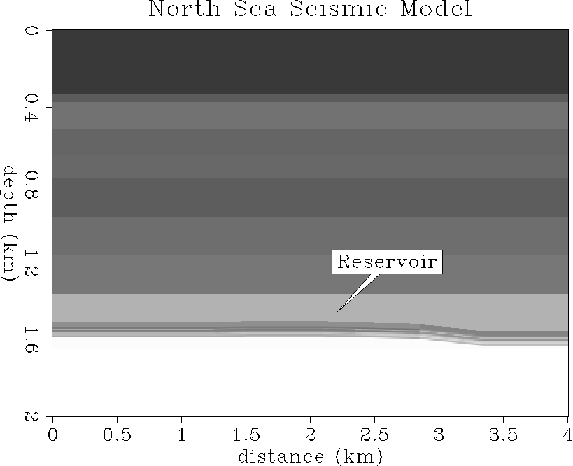
North Sea seismic model
A global seismic model of P- and S-wave velocity and density
was constructed based on information provided by Norsk Hydro,
as shown in Figure . The global model
consists of a 1-D ``overburden'' macro-model merged with a 2-D fine-scale
reservoir model.
A vertically-stratified ``overburden'' model was designed
to optimize intensive synthetic seismogram computation while still
preserving the overall character of the stacked section and the simple
v(z) interval velocity model provided by Norsk Hydro. The macro-layers
of the overburden model were chosen to approximate the position
and relative reflection amplitude of reflectors seen in the
Norsk Hydro stacked section at the well location, which penetrates the
reservoir horizontally at about 1.55 km depth at the 1.5-2.0 km midpoint
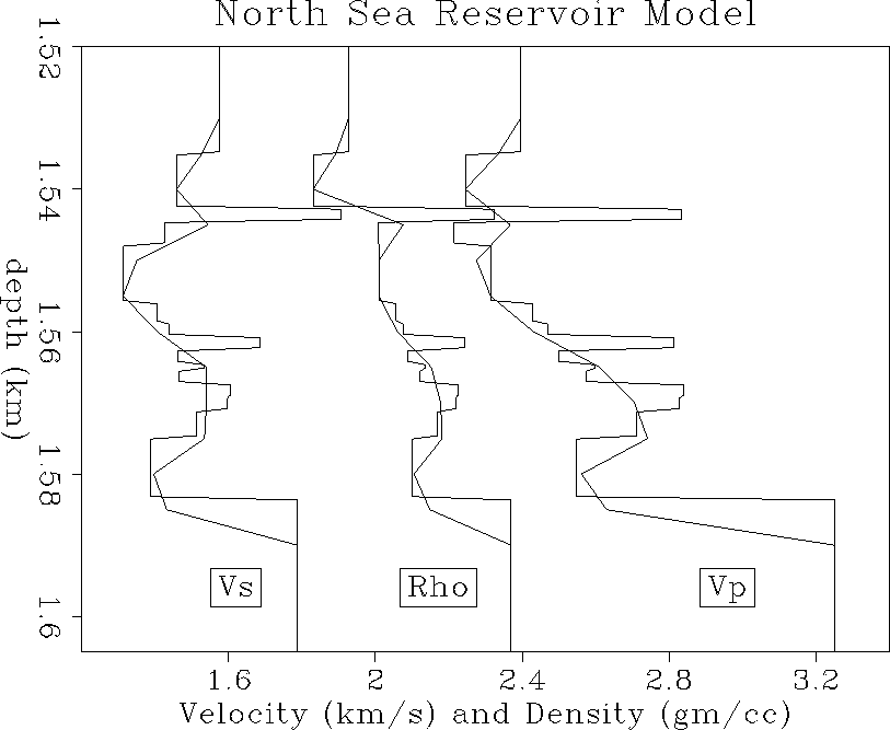
distance in the coordinate system shown in Figure .
Vp1-ann
Figure 38 P-wave velocity model consisting of
a 1-D ``overburden'' structure and a 2-D fine-layered reservoir zone
at 1.5-1.6 km depth.
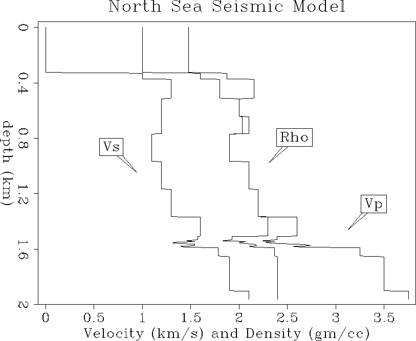
Three curves of Vp, Vs and density are shown at the well location
as a function of depth in Figure .
The 1-D overburden increases slowly with depth
down to the top of the reservoir, with a slight low velocity zone in the
middle depth section. The reservoir zone at 1.55 km depth has a
strong low velocity
and density contrast due to the gas cap, and then increases to
a regional profile at and below the base of the reservoir.
curves0-ann
Figure 39 Initial velocity and
density model at the surface well position (2 km).
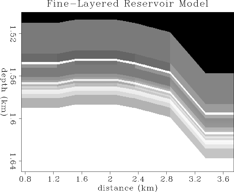
Upscaled reservoir model
Figure shows a fine-layered model of P-impedance calculated
from the fluid-flow simulations provided by Norsk Hydro. The fine-scale
seismic properties were mapped from reservoir pressure, temperature,
relative saturation values of oil, water and gas, and porosity as
described by the previous rock physics section of this report.
res1
Figure 40 P-impedance reservoir model
evaluated on a fine grid mesh.
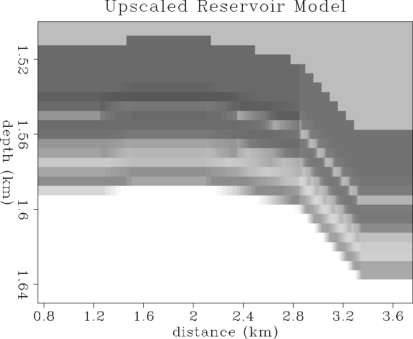
An issue of upscaling arises because in situ reservoir properties measured
at very small spatial scales are not necessarily the same properties
that a seismic wavefield samples at larger seismic wavelength scales.
The reservoir simulation used a grid mesh that represented fine-layering
on a scale as small as 1 meter in thickness. It would be computationally
prohibitive to compute prestack seismograms on a mesh that small, and
may not be numerically justifiable even if one could do so.
Instead, we consider an ``equivalent medium'' sampled on a
coarse mesh that propagates seismic wavefields which are dynamically
equivalent to the waves that would have propagated in the true
fine-layered medium. This equivalent medium can be approximated by
a spatially weighted average of elastic compliance and density
which attempts to conserve the stress-strain energy of elastic waves
and the mass of the medium (Schoenberg and Muir, 1989; Muir et al., 1992).
Figure shows the upscaled coarse-mesh equivalent
reservoir model of P-impedance. Similar upscaled
equivalent models were calculated for S-impedance and density.
Figure shows the fine-scale and upscaled
Vp, Vs and density curves in the reservoir at the wellbore location.
The upscaling was done as follows. First, an over-sampled representation
of the fine scale reservoir model was obtained at a sampling
interval of 0.5 m in depth and 2.5 m in midpoint distance.
Next, the equivalent medium averaging was done for isotropic elastic
compliance and density onto a coarse mesh of 5 m by 5 m in depth and
midpoint. The upscaled compliances were then converted to P- and S-impedance
to give the final upscaled seismic models at a mesh interval that is about
one tenth of a seismic wavelength, as opposed to the original 1/100th
of a seismic wavelength.
res2
Figure 41 Upscaled P-impedance reservoir
model on a coarse grid mesh. Obtained by
averaging elastic compliance and density from fine to
coarse mesh scales.
bgcurves-ann
Figure 42 Reservoir velocity
and density model curves. Blocky curves are fine-mesh values at
0.5 m depth intervals, smooth curves are equivalent
upscaled values at 5 m intervals.
Time-variant seismic models
Using the equivalent medium upscaling procedure described
above, P- and S-impedance, and density models were computed for
each of the three production monitoring phases. The monitors
simulate fluid flow in the reservoir due to production in a
horizontal well after one day, 56 days, and 113 days of production.
For simplicity, we name the day-one simulation as the ``base survey'',
and the subsequent 56 and 113 day monitors as ``monitor 1'' and
``monitor 2'' respectively.
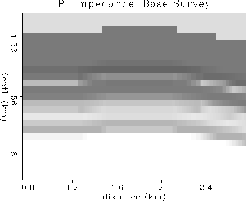
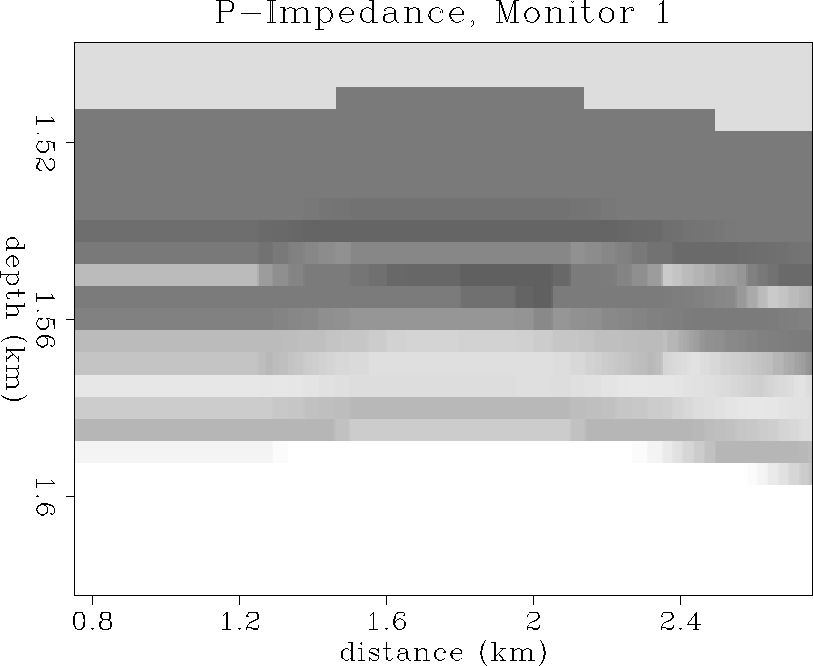
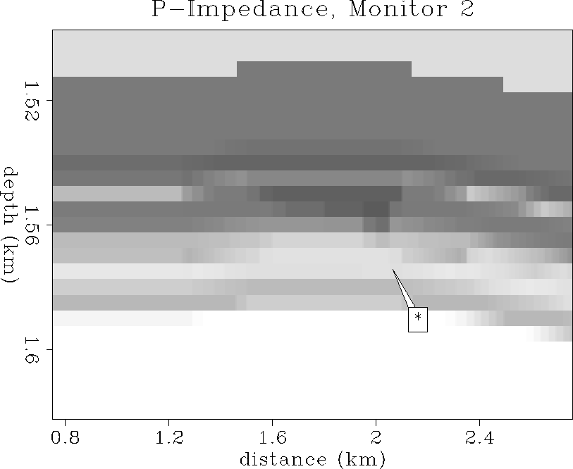
P-impedance
Figure shows the initial state of seismic P-impedance (Ip).
Figures and show the Ip distributions after
56 and 113 days of oil production. In the vicinity
of the wellbore, an asymmetric decrease in P-impedance is evident
during production. This decrease in P-impedance is more clearly
shown at 2 km in the curves of Figure . The
decrease in P-impedance is due to downward coning and
enlargement of the gas cap near the wellbore
during production of the thin oil zone, and the asymmetry is probably
due to lateral change in perforation density along the horizontal well.
During the total production time, the P-impedance decreases in the reservoir
by a maximum relative contrast of about 15%, and is spread over
a zone that is approximately 500 m wide and 15 m thick.
This change in P-impedance will be shown later to cause
a significant seismic reflection response.
ip1
Figure 43 Initial P-impedance distribution in
enlarged reservoir zone. Ip ranges from 3.8 (dark gray)
to 7.8 km/s-g/cc (white).
ip2
Figure 44 P-impedance distribution after 56 days
of oil production. The averaged Ip values have decreased
by about 10% in the production interval.
ip3-ann
Figure 45 P-impedance distribution after 113 days
of oil production. The averaged Ip values have decreased
by about 15% in the production interval.
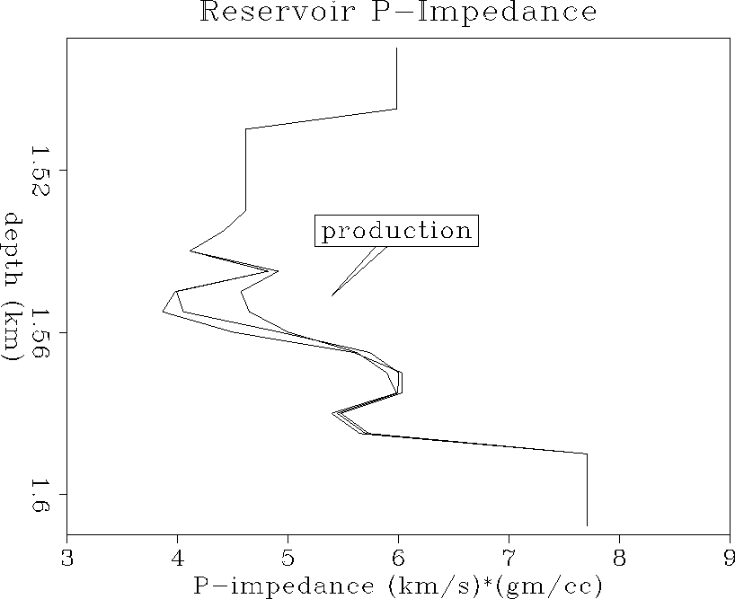
ipcurves-ann
Figure 46 Reservoir time-varying
P-impedance curves. Averaged P-impedance decreases significantly
by about 10-15% with increasing production time due to gas coning.
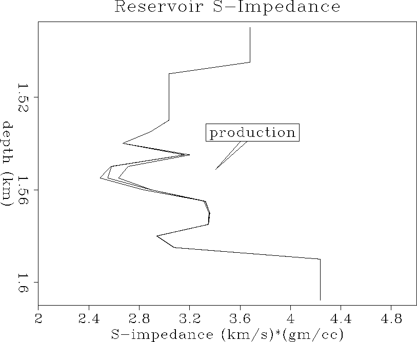
S-impedance
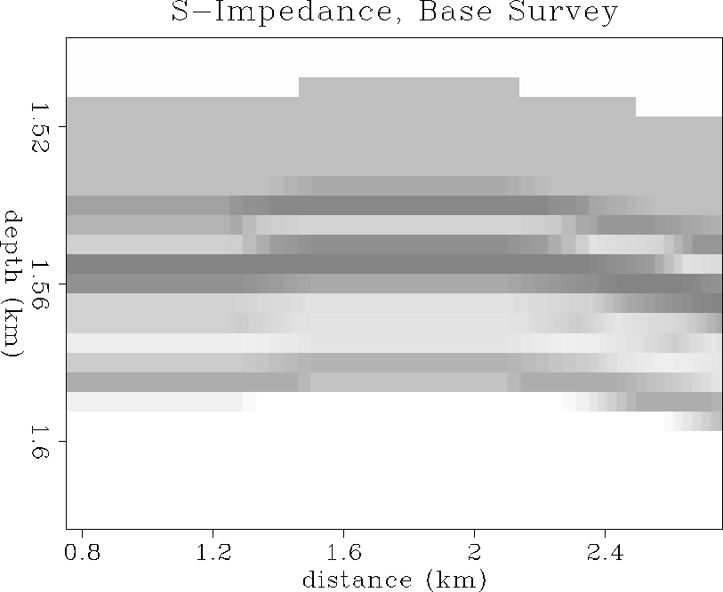
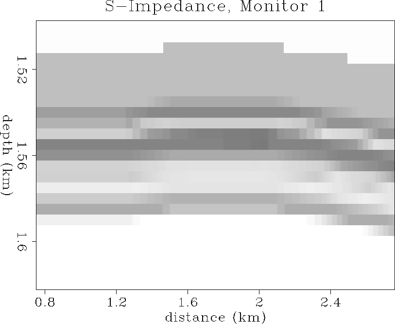
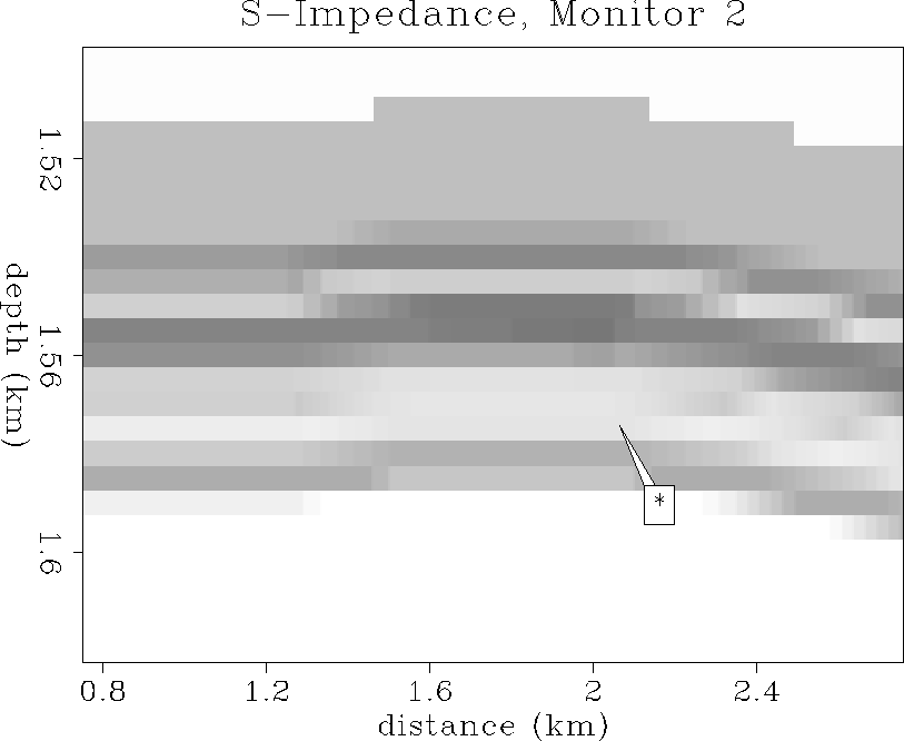
Figure shows the initial state of seismic S-impedance (Is).
Figures and show the Is distributions after
56 and 113 days of oil production.
Barely any change in S-impedance is visible in the zone of gas coning.
This is because the shear modulus is not sensitive to fluid-saturation
changes, and the pressure effect is also negligible at
these small drawdown pore pressure changes. Vs has slightly increased
due to a small decrease in density, and these two effects tend to
cancel each other for S-impedance, which is the product of Vs and density.
Thus, the overall result is a slight decrease in shear impedance during
oil-replacement by expanding gas during production.
The S-impedance curves of Figure at the well location
show that the S-impedance decreases a maximum of 5% at the cone,
but is more representatively a decrease of about 2% spread over the
entire zone of gas coning.
is1
Figure 47 Initial S-impedance distribution in
enlarged reservoir zone. Is ranges from 2.5 (dark gray)
to 4.2 km/s-g/cc (white).
is2
Figure 48 S-impedance distribution after 56 days
of oil production. The averaged Is values have decreased
by about 3% in the production interval.
is3-ann
Figure 49 S-impedance distribution after 113 days
of oil production. The averaged Is values have decreased
by about 5% in the production interval.
iscurves-ann
Figure 50 Reservoir time-varying
S-impedance curves. S-impedance decreases slightly
by about 2-5% with increasing production time due to gas coning.
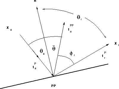
Kirchhoff seismogram modeling
Given the reservoir models during each of the three phases of oil
production, synthetic surface reflection seismic data can be
generated for each time snapshot of production.
The synthetic seismograms are calculated based on the generalized
Kirchhoff body force scattering theory of Lumley and Beydoun (1993).
This theory combines Zoeppritz plane-wave reflection and Rayleigh-Sommerfeld
elastic diffraction responses. The modeling theory can generate the correct
AVO response for locally planar reflectors, and merge into diffraction
where elastic properties vary spatially faster than a seismic wavelength.
However, since the Green's tensors are WKBJ ray-valid, only primary
reflections and diffractions are computed. Higher order
multiple scattering or phenomena such as surface waves are not modeled.
The modeling theory is based on a volume integration of the body force
equivalent of the  coefficient:
| 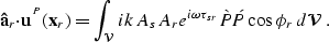 |
(21) |
 is the P-P scattered vector wavefield measured at the receiver
position
is the P-P scattered vector wavefield measured at the receiver
position  , and projected onto an arbitrary receiver component direction
 . As and Ar are the elastic WKBJ Green's function amplitudes
from the source and receiver positions respectively, to each subsurface
scattering point
. As and Ar are the elastic WKBJ Green's function amplitudes
from the source and receiver positions respectively, to each subsurface
scattering point  in the volume
  . Similarly,
 is the total traveltime from source to scatterer
to receiver. The factor
is the total traveltime from source to scatterer
to receiver. The factor  is the non-geometric diffraction angle
as shown in Figure , and is unity along the Snell reflection
path (specular), and variable otherwise. The factor is the
plane-wave Zoeppritz elastic P-P reflection coefficient, and k is
the spatial wavenumber
is the non-geometric diffraction angle
as shown in Figure , and is unity along the Snell reflection
path (specular), and variable otherwise. The factor is the
plane-wave Zoeppritz elastic P-P reflection coefficient, and k is
the spatial wavenumber  .The incident arrival direction vector
  is drawn in Figure .
The volume integration gives the impulse response seismograms
which can then be filtered to any desired bandwidth and convolved
with a wavelet.
Additionally, spatially-uncorrelated Gaussian distributed noise, filtered to
match the same frequency bandwidth as the seismic signal, may also
be added to produce fairly realistic primary reflection data with
accurate AVO responses and the presence of seismic noise.
anglegeom
Figure 51 Generalized Kirchhoff reflection
and diffraction angle geometries.
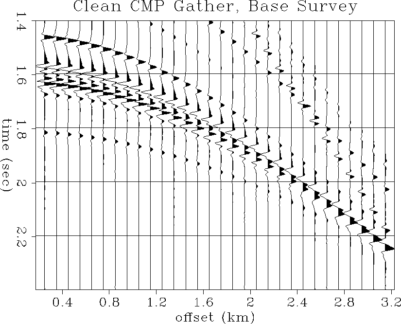
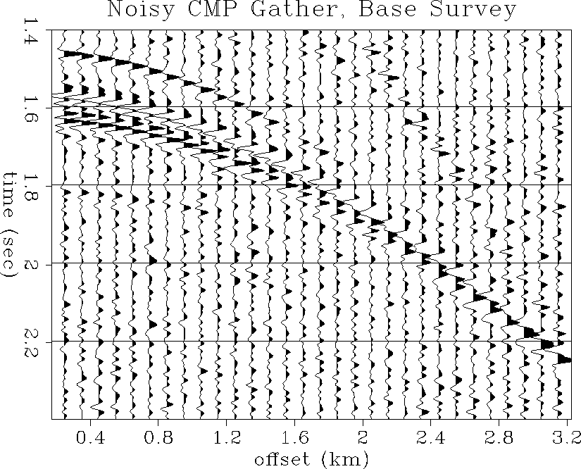
CMP gather analysis
Synthetic seismograms were generated at the CMP location directly
above maximum coning, at 2 km distance in the midpoint coordinate.
A typical marine acquisition geometry of 60-fold CMP gathers
was used with a near offset of 250 m and a 3 km cable length.
The bandwidth of the seismic data have corner frequencies of
5, 10, 60 and 80 Hz. Random spatially-uncorrelated Gaussian
noise was filtered to the same bandwidth and added to make the
``noisy'' seismic traces. The signal-to-noise (S/N)
amplitude ratio is about 3:1 at the main reservoir reflections at 1.6 seconds.
For display purposes, the CMP gathers have been divergence-corrected
and compensated for source-receiver amplitude directivity.
Figure shows a close-up of the reservoir reflections
in the noise-free CMP gather at the time of the base survey.
Figure shows the same CMP gather but with added
noise. The top of the reservoir is the first negative reflection at
about 1.55 seconds, and the complex wavetrain following is due
to the fine-layered nature of the reservoir zone. Since the
velocity increases dramatically from the top to the bottom
of the reservoir, the reservoir reflections tend to coalesce into
one single low-frequency high-amplitude waveform at far offsets.
The reservoir reflections are still prominent in the noisy
CMP gather, although the shallower arrivals at far offsets are not.
clean1
Figure 52 Noise-free CMP gather at the
well location: base survey.
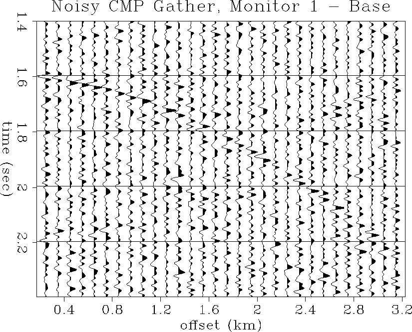
noise1
Figure 53 Noisy CMP gather at the
well location: base survey.
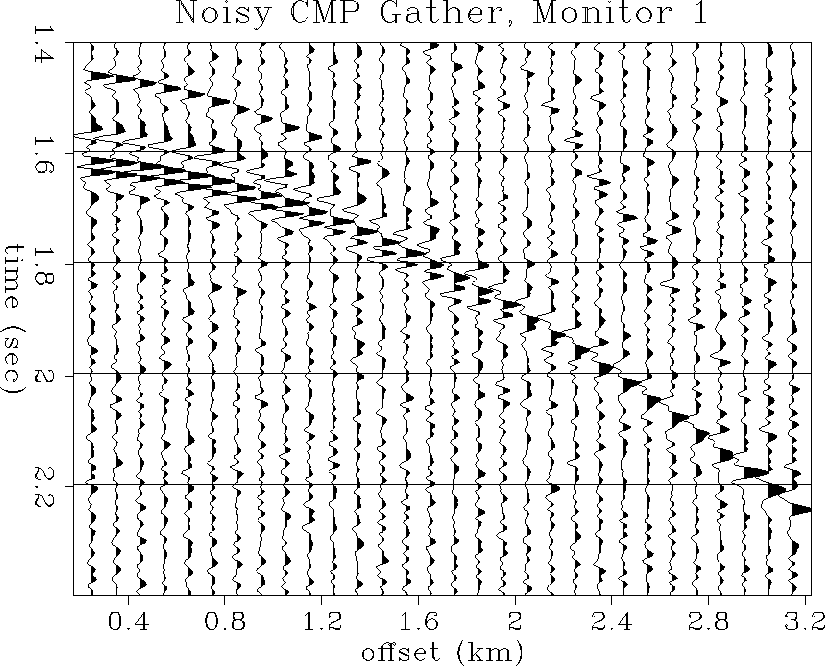
Figures and show the same CMP gathers
at the time of monitor 1. Due to the decrease in P-impedance,
the negative reflection at 1.6 seconds, slightly below the top of
the reservoir, has increased in magnitude, as has its positive side-lobe
at about 1.61 seconds. There is also an apparent increase in
wavetrain amplitude with offset, compared to the base survey CMP gathers.
Both the increased near-offset reflection amplitude and the AVO
enhancement are visible in the noisy CMP gathers.
clean2
Figure 54 Noise-free CMP gather at the
well location: first monitor survey.
noise2
Figure 55 Noisy CMP gather at the
well location: first monitor survey.
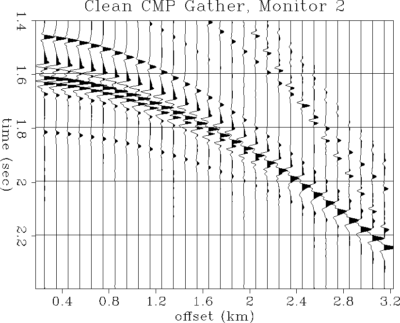
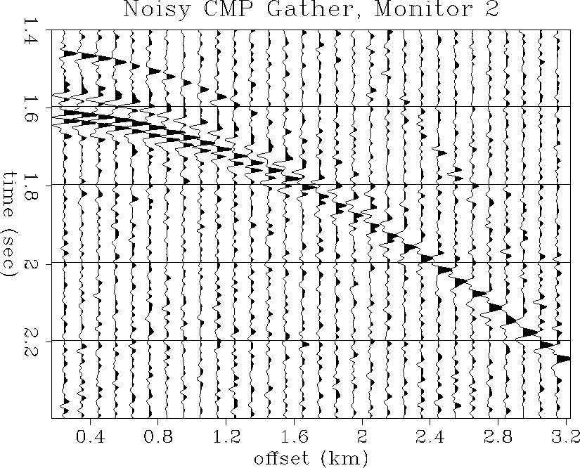
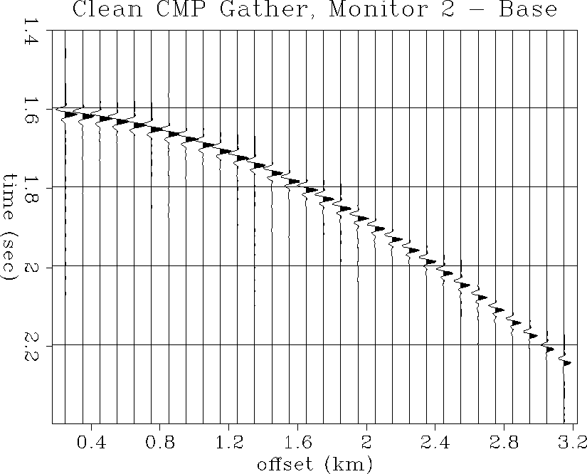
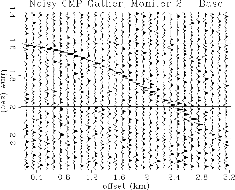
Figures and show the same CMP gathers
at the time of monitor 2. Again, due to the decrease in P-impedance,
there is an increase in near-offset amplitude and AVO, although
not perceptibly different than monitor 1 from this view in the
CMP gathers.
clean3
Figure 56 Noise-free CMP gather at the
well location: second monitor survey.
noise3
Figure 57 Noisy CMP gather at the
well location: second monitor survey.
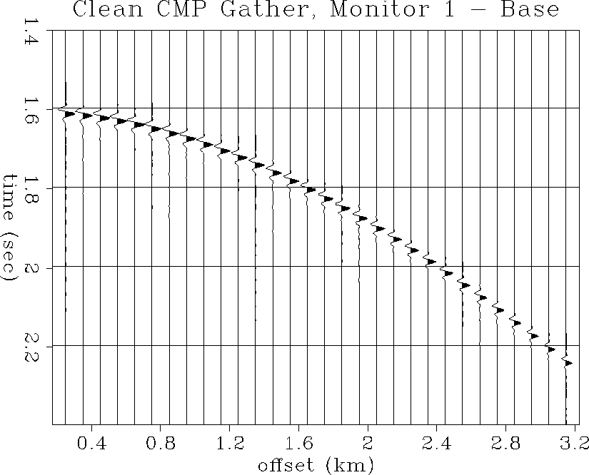
Figures and show the ``difference gathers''
obtained by subtracting the CMP gathers of the base survey from
those of monitor 1. A single Hilbert-shaped diffraction waveform expresses the
difference between the two surveys. The dipole Hilbert shape
arises from a negative P-impedance contrast at the top of the coning
zone, followed closely by an increase in P-impedance in the
unchanged reservoir at the base of the cone. The difference diffraction
is visible in the noisy data with a S/N ratio of about 1.5:1.
clean12
Figure 58 Difference gather obtained
by subtracting the noise-free base survey gather from the first
monitor gather.
noise12
Figure 59 Difference gather obtained
by subtracting the noisy base survey gather from the first
monitor gather.
Figures and show the difference gathers
obtained by subtracting the CMP gathers of the base survey from
those of monitor 2. A stronger dipole diffraction waveform expresses the
difference between the two surveys, which is clearly visible in
the noisy data with a S/N ratio of about 2:1.
clean13
Figure 60 Difference gather obtained
by subtracting the noise-free base survey gather from the second
monitor gather.
noise13
Figure 61 Difference gather obtained
by subtracting the noisy base survey gather from the second
monitor gather.
Stacked section analysis
Three prestack marine surveys were simulated to monitor the oil production
in the North Sea reservoir. Each survey consisted of 161 60-fold CMP gathers
with noise, as described in the previous section. The midpoint spacing
was 25 m such that the 161 CMP gathers in each survey covered a total
line length of 4 km. Each gather had a
minimum source-receiver offset of 250 m and a maximum offset of 3.250 km,
and a total record length of 2.4 seconds at a 4 ms sample interval.
The prestack data were muted at water velocity, divergence corrected,
and amplitude corrected for source and receiver directivity prior to stacking.
No wavelet deconvolution was applied. A 1-D rms stacking velocity was
computed from the 1-D overburden interval velocity model, without the
detailed 2-D reservoir zone velocity variations, and was used to perform the
anti-aliased NMO stack. This emulates a standard processing sequence
in which only macro velocity information is known prior to stacking
and migration.
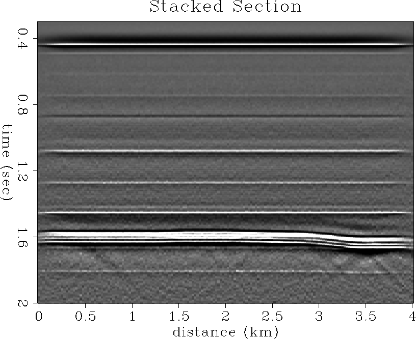
Figure shows the complete stacked section from the base survey,
which is a fairly good but idealized approximation to the real stacked
paper section provided by Norsk Hydro.
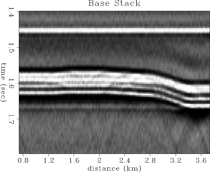
Figure shows a close-up of the reservoir in the base survey
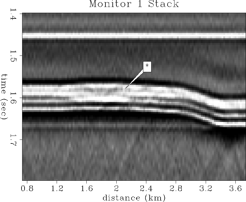
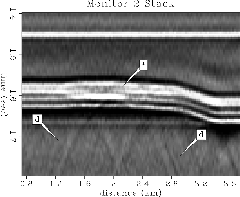
stacked section. Figures and show the
same reservoir close-up of the monitor 1 and 2 stacked sections respectively.
Subtle changes in the form of increased bright amplitudes in the stacked
section are evident in the vicinity of the wellbore and gas coning at 2 km
and 1.6 s. Also, some diffraction tails are present due to the
point-source-like, strong impedance contrast at the lower tip of the
gas cone, and are especially evident in the monitor 2 stack.
Stack1
Figure 62 Base survey stacked section.
stack1
Figure 63 Base survey stacked section.
stack2-ann
Figure 64 Monitor 1 stacked section.
Note the bright amplitudes due to gas coning.
stack3-ann
Figure 65 Monitor 2 stacked section.
Note the development of diffractions ``d'' from the gas cone.
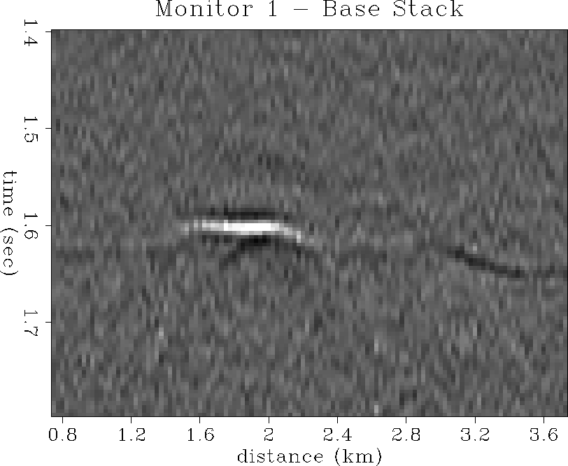
Figure shows the difference section obtained by a simple
subtraction of the base survey stack from the monitor 1 stack.
The gas coning clearly stands out from the background seismic noise
as a bright spot at 2 km and 1.6 s. A small diffraction tail is present
at the tip of the gas cone. There are also some low amplitude seismic
differences at the lateral edges of the reservoir. These seismic difference
amplitudes are due directly to pressure and saturation changes calculated
in the fluid-flow simulation, and are not seismic modeling or processing
artifacts. These boundary pressure and saturation changes may be
low-amplitude fluid-flow simulation artifacts caused by a sparse
simulation mesh or imperfect boundary conditions in the fluid-flow
modeling algorithm, since they are visible in the simulation data.
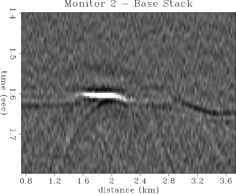
Figure shows the stacked difference section comparing monitor 2
to the base survey. The amplitude of the main bright spot and
its diffraction tails has increased considerably, and is clearly
identifiable from the background noise.
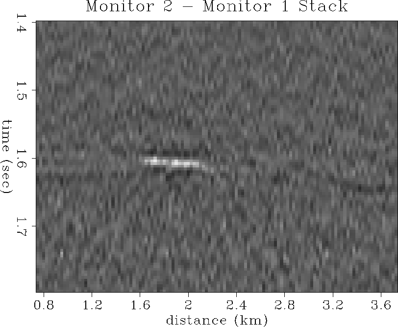
At the same plotting scale, Figure shows the stacked difference
section comparing the seismic change between monitor 2 and monitor 1.
The main gas cone anomaly is quite weak, which indicates that the
major seismic response to oil production occurs between monitor 1
and the base survey. Monitor 2 adds extra information on the lateral
extent, depth, and thickness of the gas cone, but the major
``detection'' of reservoir change occurs by the time of monitor 1 (56
days into production).
stack12
Figure 66 Base survey stacked section
subtracted from the first monitor stacked section.
Note the bright amplitudes due to gas coning.
stack13
Figure 67 Base survey stacked section
subtracted from the second monitor stacked section.
Note the increased bright amplitudes and diffractions due to
gas coning.
stack23
Figure 68 First monitor stacked section
subtracted from the second monitor stacked section.
Note the weak amplitudes due to gas cone movement between
monitor surveys.
Prestack migration analysis
The same three prestack datasets described in the previous section
were analyzed after prestack migration. Preprocessing included a
simple water-velocity mute. No geometrical-spreading correction
or source-receiver amplitude directivity were compensated for
in the preprocessing phase, since the prestack migration code
incorporates these corrections in a more physical manner.
A true-amplitude Kirchhoff prestack migration code was used that includes
operator anti-aliasing (Lumley, 1993; Lumley and Claerbout, 1993).
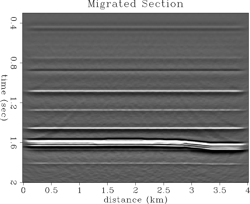
Figure shows the complete prestacked-migrated section
from the base seismic survey. Figure shows a close-up of
the reservoir zone in the base survey migrated section. In comparison
with the base stack of Figure , one can see the improvement
in S/N ratio and spatial resolution of the reservoir boundaries and
internal reflections that prestack migration brings.
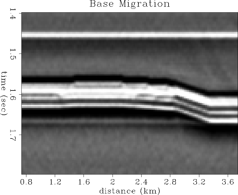
Figures and show the prestack migrated
reservoir sections from the monitor 1 and monitor 2 surveys
respectively. There is a well-defined increase in bright-spot
amplitude at the position of the gas cone, and its spatial resolution
is very good compared to the original time-variant impedance models.
The migrated sections are not cluttered with diffraction noise as was
the case with the stacked sections, and the resolution of the
gas cone anomaly is much higher than the blurred stacked section response.
This is because stacked seismic data have a resolution on the range
of about 1/4 of a Fresnel zone (typically hundreds of meters),
whereas prestack migrated images have a resolution on the order of
1/4 of a seismic wavelength (typically tens of meters).
Mig1
Figure 69 Base survey migrated section.
mig1
Figure 70 Base survey migrated section.
mig2-ann
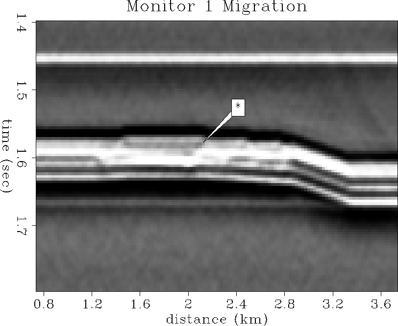
Figure 71 Monitor 1 migrated section.
Note the bright amplitudes due to gas coning.
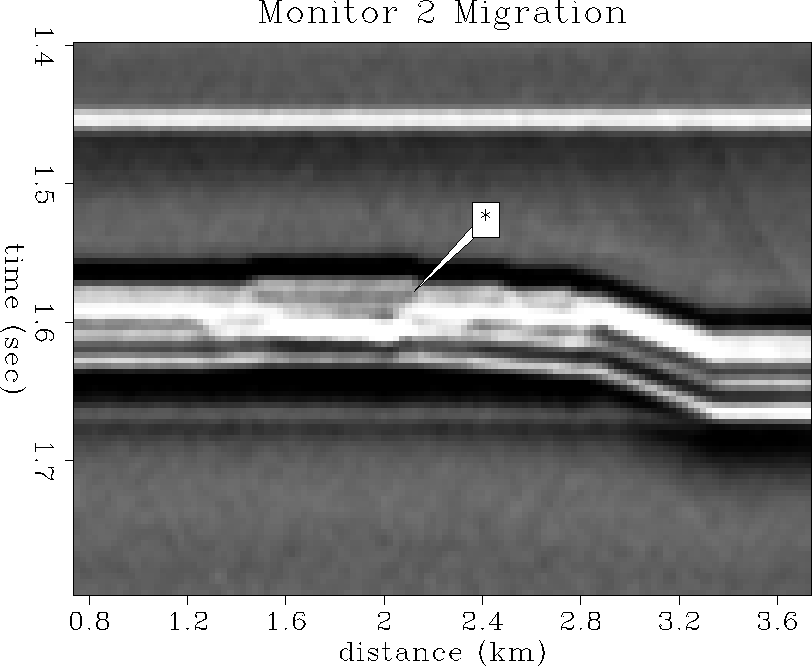
mig3-ann
Figure 72 Monitor 2 migrated section.
Note the increased bright amplitudes due to gas coning.
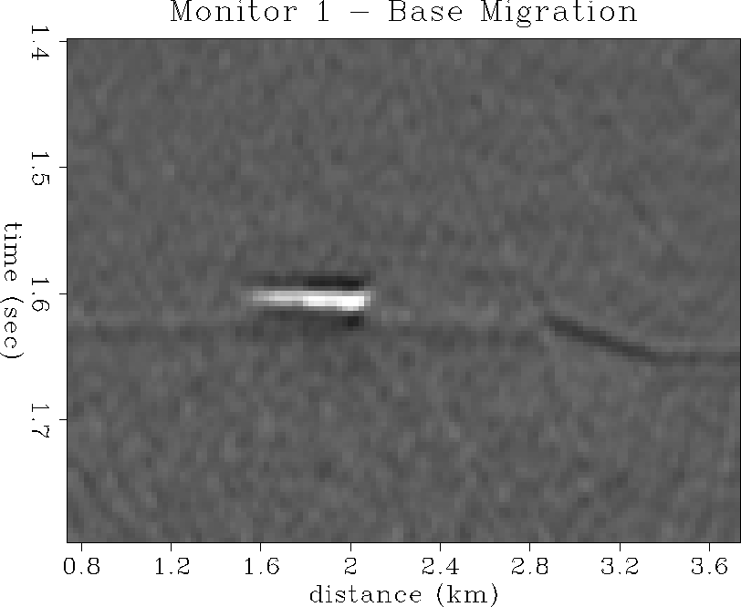
Figure shows the difference section obtained by a simple
subtraction of the base survey migration from the monitor 1 migration.
The gas coning clearly stands out from the background seismic noise
as a bright spot at 2 km and 1.6 s, and accurately defines
the spatial extent of the true impedance model anomaly.
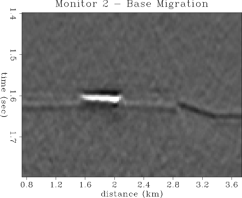
Figure shows the difference section comparison
between the monitor 2 and base survey migrations.
Again, the seismic response to the gas coning is very clear and
accurate in spatial location.
Figure shows the change in migrated seismic response
between the first and second monitor surveys. As with the stacked
section analysis, most of the major detectable seismic response
occurs by the time of the first monitor survey, and the difference between
the first and second monitors is a more subtle expression of the
increase in spatial extent and impedance anomaly of the expanding gas
cone.
mig12
Figure 73 Base survey migrated section
subtracted from the first monitor migrated section.
Note the bright amplitudes due to gas coning.
mig13
Figure 74 Base survey migrated section
subtracted from the second monitor migrated section.
Note the increased bright amplitudes due to gas coning.
mig23
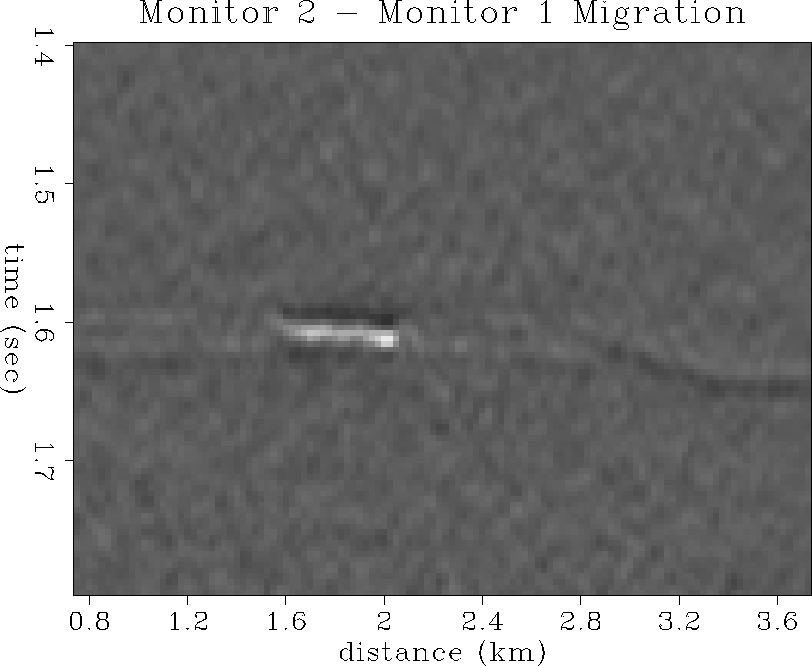
Figure 75 First monitor migrated section
subtracted from the second monitor migrated section.
Note the weak amplitudes due to gas cone movement between
monitor surveys.
Seismic conclusions
This section of the paper discussed the feasibility of performing
a seismic monitoring analysis of the North Sea reservoir in simulated
oil production, based on prior fluid-flow simulation and rock physics
results. To test seismic monitoring feasibility, detailed reservoir
models of elastic impedance and density were constructed that honored
the fluid-flow pressure and saturation data, combined with rock physics
data and petrophysical relationships. Prestack synthetic seismic
surveys were then generated for each of the three production phases:
base survey (no production), monitor 1 (56 days of production),
and monitor 2 (113 days of production).
Using realistic marine seismic
recording geometry parameters and noise levels, we were able to
successfully detect and monitor dynamic gas-cone movement in the
reservoir from seismic monitor data during the fluid-flow simulation
of oil production.
Evidence of gas-cone evolution is clearly visible in both the
stacked and prestack-migrated seismic difference sections at
realistic seismic noise levels and seismic frequency bandwidth.
In particular,
the prestack migrated sections have enough spatial resolution
to accurately locate the lateral extent, depth and thickness
of the developing gas cone.
If a simple detection of reservoir change is the first order goal, then
this could be reasonably achieved after only 56 days of production
by comparing the base seismic survey stacked section to the first monitor
survey stacked section using the differencing technique.
If, however, a clear image of the dynamic gas-cone evolution
is desired, repeated seismic monitoring of oil production is needed
to increase the S/N ratio of the seismic gas-cone response,
and robust prestack-migration imaging is required to optimally estimate the
spatial extent and amplitude of the evolving gas-cone impedance anomaly.
CONCLUSIONS
We conducted a feasibility study concerned with the likelihood of
seismically detecting and monitoring the fluid-flow changes in a
North Sea reservoir during solution-gas-drive oil production from a
horizontal well.
We conducted this hydrocarbon recovery monitoring analysis by:
(1) using flow simulation results (pore pressure, and oil, gas and water
saturations) and information about the relevant rock properties
(dry elastic constants); (2) using rock physics to compute compressional
and shear wave impedances in the reservoir from the flow simulation results;
(3) conducting elastic modeling to simulate seismic surveys of the
recovery process; and (4) mapping the differences between seismic responses
at production intervals of 56 and 113 days, and the base seismic survey.
Using realistic marine seismic recording geometry parameters and noise levels,
we were able to successfully detect and monitor dynamic gascap coning
and expansion in the reservoir from seismic monitor data during the
fluid-flow simulation of oil production.
Feasibility studies such as this may help reduce the financial risk
associated with designing and implementing a seismic monitoring project
given a pre-monitor engineering and petrophysical reservoir database.
ACKNOWLEDGMENTS
We thank Norsk Hydro for providing us with the reservoir information
and fluid-flow simulation data in order to undertake this project.
This work was supported by Norsk Hydro and the Sponsors of the
Stanford Exploration Project.
We thank Francis Muir, Gary Mavko and Tapan Mukerji for useful
discussions and assistance related to this study.
REFERENCES
-
Blangy, J. P., 1992, Integrated seismic lithologic interpretation:
the petrophysical basis, Ph.D. Thesis, Stanford University.
-
Blangy, J. P., and Strandenes, S., 1991, Stanford Rock Physics Lab Report,
47, Stanford University.
-
Bourbié, T., Coussy, O., and Zinszner, B., 1987, Acoustics of porous
media: Institut Francais du Petrole Publications.
-
Eastwood, J., Lebel, P., Dilay, A., and Blakeslee, S., 1994,
Seismic monitoring of steam-based recovery of bitumen:
The Leading Edge, 13, 242-251.
-
Graebner, R., 1993, Geophysics: The potential and limits for reservoir
description and monitoring: presented at the 1993 Annual Summer
Research Workshop, Soc. Expl. Geophys.
-
Greaves, R. J., and Fulp, T. J., 1987, Three-dimensional seismic monitoring
of an enhanced oil recovery process: Geophysics, 52, 1175-1187.
-
Han, D., 1986, Effects of porosity and clay content on acoustic properties
of sandstones and unconsolidated sediments: Ph.D. Thesis,
Stanford University.
-
Lumley, D. E., 1993, Kirchhoff prestack impedance inversion: a gas reservoir
pilot study: Stanford Exploration Project Report, 77,
Stanford University, 211-230.
-
Lumley, D. E., and Beydoun, W. B., 1993, Angle-dependent reflectivity
estimation by Kirchhoff migration/inversion: Stanford Exploration
Project Report, 79, Stanford University, 205-226.
-
Lumley, D. E., and Claerbout, J. F., 1993, Anti-aliased Kirchhoff 3-D
migration: a salt intrusion example: Annual SEG Summer Research
Workshop on 3-D Seismology, Soc. Expl. Geophys., Expanded Abstracts,
115-123.
-
Muir, F., Dellinger, J., Etgen, J., and Nichols, D., 1992, Modeling elastic
fields across irregular boundaries: Geophysics, 57, 1189-1193.
-
Nur, A., 1989, Four-dimensional seismology and (true) direct detection
of hydrocarbons: the petrophysical basis: The Leading Edge, 9,
30-36.
-
Pullin, N. E., Jackson, R. K., Matthews, L. W., Thorburn, R. F.,
Hirsche, W. K., and den Boer, L. D., 1987, 3-D seismic imaging
of heat zones at an Athabasca tar sands thermal pilot: 57th
Annual Internat. Mtg., Soc. Expl. Geophys., Expanded Abstracts,
391-394.
-
Schoenberg, M., and Muir, F., 1989, A calculus for finely layered anisotropic
media: Geophysics, 54, 581-589.
Next: About this document ...
Up: Table of Contents
Stanford Exploration Project
5/15/2001