

Next: Load balance
Up: DMO BY TIME SLICE
Previous: DMO BY TIME SLICE
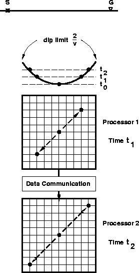
The memory layout for processing time slices is illustrated
in Figure ![[*]](http://sepwww.stanford.edu/latex2html/cross_ref_motif.gif) . The time slices are local to each processor
and the time axis is the parallel dimension.
Thus, the number of processors needed is the number of time samples,
and the memory of each processor must be large enough to load and
process one time slice. When the amount of data exceeds the memory
available, the process can run on lumps of data. The lumps may
be pieces of data cut in the (x,y) space, preserving the parallel axis
and relieving the processors memory, or they may be cut in time,
shortening the parallel axis but requiring a smaller area of overlap
between successive lumps.
. The time slices are local to each processor
and the time axis is the parallel dimension.
Thus, the number of processors needed is the number of time samples,
and the memory of each processor must be large enough to load and
process one time slice. When the amount of data exceeds the memory
available, the process can run on lumps of data. The lumps may
be pieces of data cut in the (x,y) space, preserving the parallel axis
and relieving the processors memory, or they may be cut in time,
shortening the parallel axis but requiring a smaller area of overlap
between successive lumps.
tsproc
Figure 3 The top-most drawing
represents the elliptic dip-limited DMO operator.
I assume that the offset line bisects the x- and y- axes
on the Earth's surface. Below, the two grids represent the
data layout inside the processors. Each processor contains
a time slice of data. Processor 1 contains the time slice
at t=t0 and performs the data communication across the (x,y)
space that corresponds to a vertical shift from t0 to t1.
During this time, processor 2 performs the same kind of operation
for a vertical shift from t1 to t2. Then, processor 1
sums its output in the output volume and communicates its input
to processor 2. The action is then repeated, moving the data
across the (x,y) space for a vertical shift from t0 to t2.
|
|  |

Unlike the previous algorithm, data communication is performed
in a single direction, up the time axis, and does not depend on
the offset and azimuth distribution. The long ranging and chaotic
communications in the (x,y) space take place in-processor.
Thus, the processing of time slices results in a more efficient
inter-processor communication than the trace processing.


Next: Load balance
Up: DMO BY TIME SLICE
Previous: DMO BY TIME SLICE
Stanford Exploration Project
11/16/1997
![[*]](http://sepwww.stanford.edu/latex2html/cross_ref_motif.gif) . The time slices are local to each processor
and the time axis is the parallel dimension.
Thus, the number of processors needed is the number of time samples,
and the memory of each processor must be large enough to load and
process one time slice. When the amount of data exceeds the memory
available, the process can run on lumps of data. The lumps may
be pieces of data cut in the (x,y) space, preserving the parallel axis
and relieving the processors memory, or they may be cut in time,
shortening the parallel axis but requiring a smaller area of overlap
between successive lumps.
. The time slices are local to each processor
and the time axis is the parallel dimension.
Thus, the number of processors needed is the number of time samples,
and the memory of each processor must be large enough to load and
process one time slice. When the amount of data exceeds the memory
available, the process can run on lumps of data. The lumps may
be pieces of data cut in the (x,y) space, preserving the parallel axis
and relieving the processors memory, or they may be cut in time,
shortening the parallel axis but requiring a smaller area of overlap
between successive lumps.
