![[*]](http://sepwww.stanford.edu/latex2html/cross_ref_motif.gif) .
.
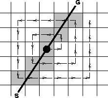
Since the irregularity of 3-D land data appears in both azimuth and offset distributions, there is no prreferential direction for data movement. Hence, Biondi had the idea of a spiral data movement alternating the shifts along the x- and y- axes. The algorithm can be outlined as follows:
![[*]](http://sepwww.stanford.edu/latex2html/cross_ref_motif.gif) .
.
|
spiral
Figure 2 Spiral pattern for data movement over output space. The shaded squares represent the processors that actually perform the stretch and the stack to the output. The white squares represent the processors that stay idle during the movement of the trace. |  |