


A diffractor in the subsurface scatters the energy of an incident wave. For a constant velocity subsurface, such a diffractor causes a perfect hyperbola in the recorded time section. The hyperbola's apex is at the lateral position of the diffractor independent of the the actual shot location. The hyperbolic shape of the event is caused by the differences in traveltime of rays from the diffractor to individual geophones. Varying the shot location at the surface changes the traveltime of the ray from the shot to the diffractor, shifting the hyperbola vertically without affecting its shape or lateral position.
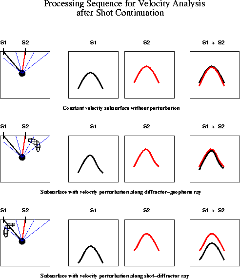 |

The left uppermost frame of Figure 1 depicts schematically the raypaths connected with two shots, s1, s2, in a constant velocity medium with a single diffractor. The two center frames of the top row show the two recorded shot gathers. After extrapolation of shot gather s1 to shot gather s2 using shot continuation, the hyperbolic events coincide, as it is indicated by overlaying the two gathers in the fourth frame.
In the center row of Figure 1, a velocity perturbation along geophone rays distorts the hyperbolic moveout in both shot gathers. Since the events in both shot gathers are distorted identically, the shot gathers nevertheless coincide after shot continuation has been applied. In the bottom row of Figure 1, however, a velocity perturbation along a shot ray causes an additional relative time shift of the two hyperbolic events. After continuation of shot s1 to shot location s2, the two events are parallel but shifted in time.
In the case of a more complex subsurface, these shifts are detected by
choosing a vertex position, extracting a local hyperbolic window in
both equivalent gathers and correlating them by shifting along the time
axis. The time shift ![]() which yields the maximum correlation is stored
at the vertex position.
which yields the maximum correlation is stored
at the vertex position.
Since only velocity perturbations along the shot-diffractor ray segment
cause these ![]() shifts, a simple first step to velocity inversion is
back projecting these
shifts, a simple first step to velocity inversion is
back projecting these ![]() values along the line between vertex and shot
position. Superposing the resulting time sections for different shots yields
a map displaying the difference between the actual subsurface velocity
distribution in (x,t) and the constant velocity model.
values along the line between vertex and shot
position. Superposing the resulting time sections for different shots yields
a map displaying the difference between the actual subsurface velocity
distribution in (x,t) and the constant velocity model.
In a velocity variable medium, the outlined velocity analysis scheme only approximates the true velocity. Tests on complex models and real data will have to prove its usefulness.