previous up next print clean
Next: Data Parallel Implementation Up: IMPLEMENTATION Previous: IMPLEMENTATION

Kirchhoff Datuming

The irregular geometries of land data acquired in rugged terrain make a datuming algorithm based on the Kirchhoff integral convenient. Berryhill 1979 gives the following expression for the upward continuation of a scalar wave field:  
 \begin{displaymath}
U(0,z,t)=\frac{1}{\pi}\int_{-\infty}^{\infty}dx \frac{z}{c} \frac{1}{r_x}
U(t-\frac{r_x}{c}),\end{displaymath} (1)
where U(0,z,t) is one trace of the upward continued wave field at datum elevation z and lateral position x=0. The function $U(t-\frac{r_x}{c})$is a time delayed filtered version of the input traces on the original datum. The assumptions that go into the derivation of this equation are locally valid for non-planar datums and two dimensional wave fields.

For a wave field transformation from one datum to another, the discretized form of equation (1) is a summation where each input trace Ui is weighted and time shifted. Each output trace is calculated by performing a sum of the form:  
 \begin{displaymath}
{U_j (t)= \sum_i \cos \theta_i A_i U_i(t-t_i)}\end{displaymath} (2)
where Ui(t-ti) is a filtered input trace recorded at location i along the lower datum and delayed by travel time ti. The effect of the filtering operation is to compensate for the Hankel tail. Ai is an amplitude term incorporating spherical divergence and geometric terms, $\theta_i$ is the angle between the normal to the input surface and the straight line travel time path connecting input location i and output location j, ti is the time shift corresponding to the travel time between the input and output locations.

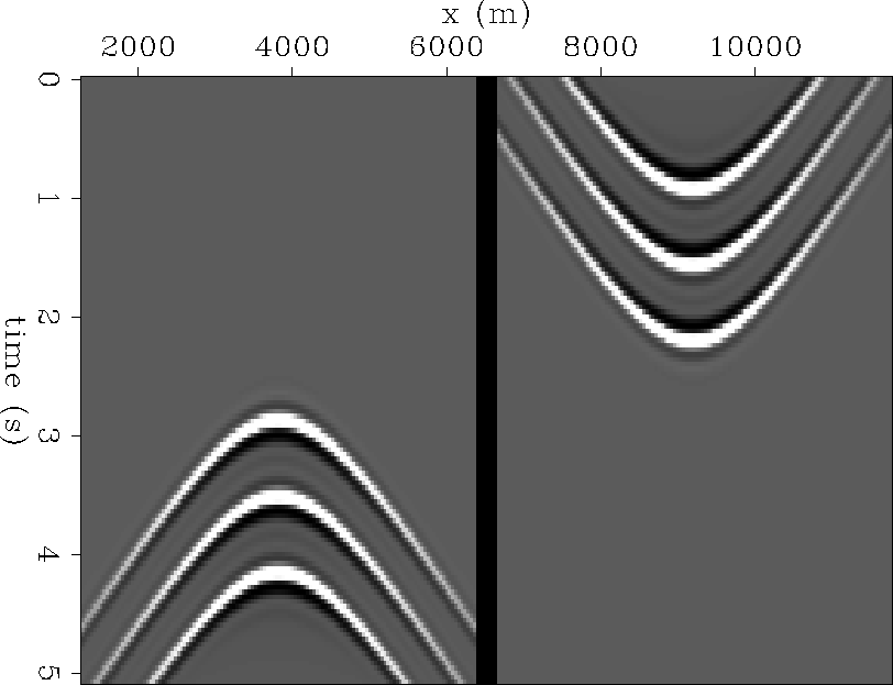
Figure 1 illustrates the impulse response of upward continuation and downward continuation for three diffractors at three different depths. The energy from each diffractor is distributed along a hyperbolic trajectory. The trajectory is the same for all depths. It is natural and convenient to do the calculation in the frequency domain because each input trace is shifted by a time invariant amount. The algorithm is cast in $\omega - x$ domain so that each individual output trace is calculated by performing a sum of the form:  
 \begin{displaymath}
{U_j (\omega)= \sum_i \cos \theta_i A_i e^{i\omega t_i} U_i(\omega)}.\end{displaymath} (3)
Because the time shift is performed in the frequency domain, there is no need to interpolate. Anti-aliasing is easily handled by filtering the input traces as necessary. Another advantage of performing the computation in the frequency domain is that a half-order differential operator is easily applied to compensate for the Hankel tail.

 
updnimp1
Figure 1
Impulse response of three diffractors at three different depths for upward continuation and downward continuation. If you have the electronic version of this document, you can press the button to see a movie of the impulse response for diffractors at different depths.
updnimp1
view burn build edit restore

Kirchhoff datuming is typically implemented in a serial fashion by looping over the input traces as indicated by equations (2) and (3). The algorithm can be applied to zero-offset data or to shot and receiver gathers. Pre-stack datuming is done by extrapolating the shots and the geophones separately using equation (3) Berryhill (1984). The extension to three dimensions is straight forward and has the same algorithmic form. Equations (1) through (3) are for upward continuation. For downward continuation the conjugate transpose process is used.


previous up next print clean
Next: Data Parallel Implementation Up: IMPLEMENTATION Previous: IMPLEMENTATION
Stanford Exploration Project
11/17/1997