


The sliding Fourier transform is widely used for extracting time-dependent spectra from time series and has localization properties similar to those of the wavelet transformations. It is described here to provide a contrast to the wavelet transforms. To create a sliding Fourier transform, a time series is cut into a series of smaller series, which are then individually Fourier transformed. This windowing creates a transformation that is localized in time.
To provide an example of this localizing feature of
the sliding Fourier transform, the trace with two spikes shown
in Figure ![[*]](http://sepwww.stanford.edu/latex2html/cross_ref_motif.gif) is shown broken up into overlapping windows in
Figure . Each window is then Fourier transformed.
This process creates the sliding Fourier transform
displayed in Figure .
is shown broken up into overlapping windows in
Figure . Each window is then Fourier transformed.
This process creates the sliding Fourier transform
displayed in Figure .
|
spike
Figure 1 A trace with two spikes. | 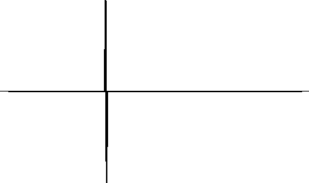 |

|
wspike
Figure 2 The trace in the previous figure windowed. Notice that the windows are overlapped and the spikes appear in two of the windows. The vertical axis is time (increasing upward) and the horizontal axis is the time corresponding to the window location, increasing to the right. | 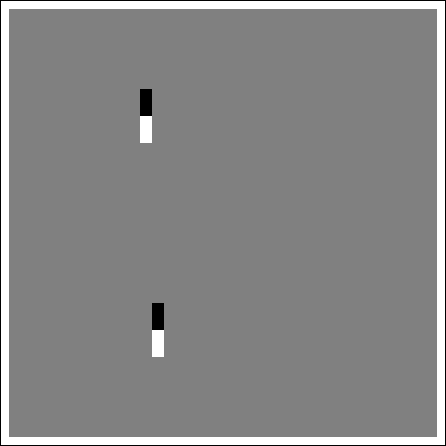 |
|
fspike
Figure 3 The traces in the previous figure Fourier transformed. This is the sliding Fourier transform. The vertical axis is frequency (increasing upward) and the horizontal axis is the time corresponding to the window location. | 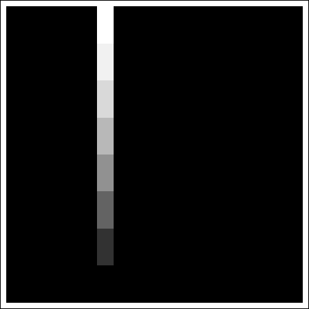 |
Figures to
show the same sequence applied to a seismic trace. Figure shows
a single seismic trace with a high amplitude zone
and a weak amplitude zone. Figure shows this trace
windowed into overlapping windows to allow the localization of
the Fourier transform.
The high amplitude zone is now separated from the low amplitude zone,
allowing the Fourier transforms
to operate within limited time ranges.
Figure shows the resulting sliding Fourier transform.
The figure shows a time separation into zones of low amplitude and
high amplitude and shows a zone of high frequency between the two zones.
This result may be compared to
the standard Fourier transform, which operates globally
on the trace and does not allow the separation of transformed events in time.
|
seis
Figure 4 A seismic trace with a low-energy zone and a high-energy zone. | 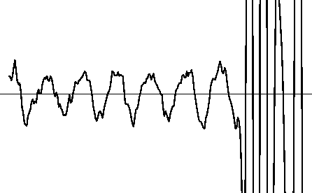 |
|
wseis
Figure 5 The trace in the previous figure windowed. Notice that the windows are overlapped and the high amplitude zone appears on the right side. | 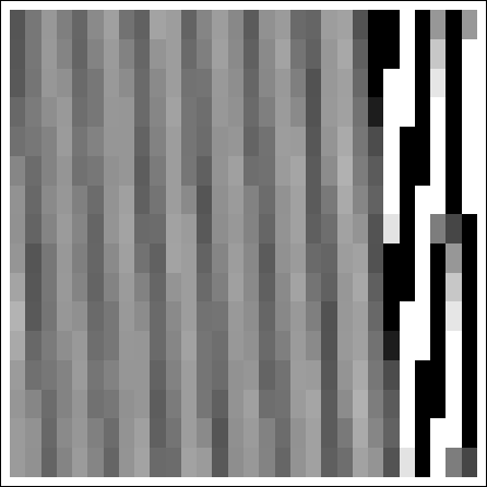 |
|
fseis
Figure 6 The traces in the previous figure Fourier transformed. This is the sliding Fourier transform. The vertical axis is frequency (increasing upward) and the horizontal axis is the time corresponding to the window location. | 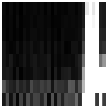 |
As the windows become smaller in the sliding Fourier transform, the frequency resolution becomes poorer. Resolution in time may be increased, but only at the expense of resolution in frequency. Another problem with the sliding Fourier transform is that the output is much larger than the input. The sliding Fourier transform is useful for analyzing frequency with respect to time, but applying an operation in the sliding-Fourier domain requires many more operations than the same application in the Fourier domain.