|
Wavelet.H
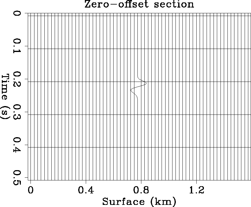
Figure 1 A record section with only one isolated wavelet. |  |
|
Wavelet.H
Figure 1 A record section with only one isolated wavelet. |  |
|
DePhase.H
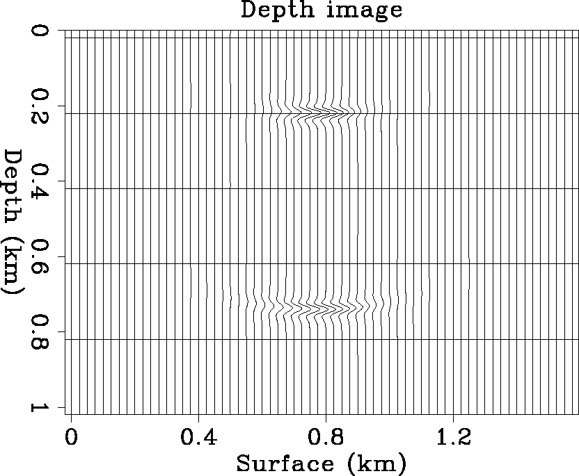
Figure 2 Migration is the process of dephasing. The Gaussian beams along one ray path can image the neighborhood. And as the Gaussian beam propagates, its parabolic wavefront spreads. |  |
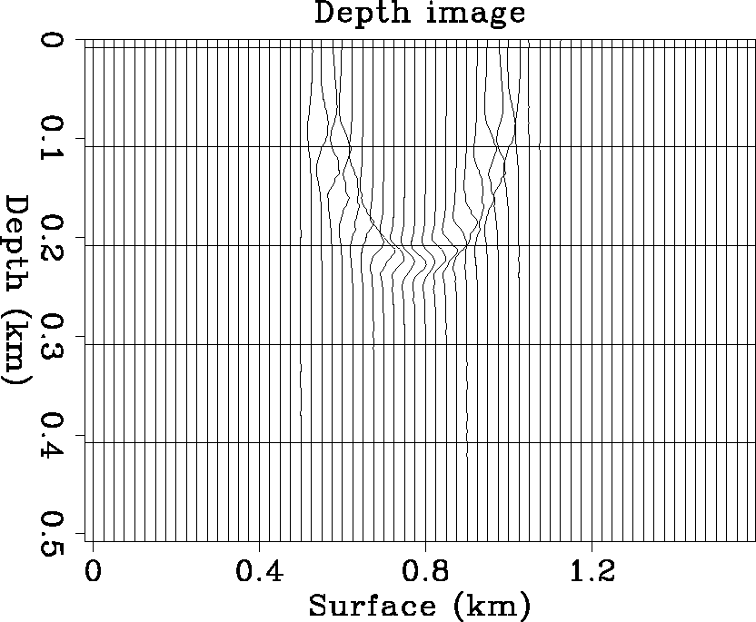
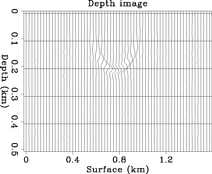
The way to avoid image reappearance is to pad with zeros at the end of the data section, and compute the depth image only to the maximum possible depth. Figure 3 is the depth image generated by migrating the above section with Gaussian beams evaluated along 51 rays from the source, equally spaced from -85 to 85 degrees. For comparison, Figure 4 displays the depth image generated by phase shift migration. In it, Stew Levin's ideas regarding how to avoid wraparound artifacts have been implemented (Levin, 1983; Claerbout, 1985). Here, because the constant velocity v=1, the output of time migration is a depth image. Kinematically, the Gaussian beam migration response correctly matches that of phase shift. However, there is some waveform distortion at high angles. The waveform distortion will be eliminated by careful coordinate interpolation of image points during construction of the Gaussian beams. An advantage of the Gaussian beam migration image over that obtained by the phase shift method is that the image background is much cleaner with Gaussian beam migration.
|
MigGB.H
Figure 3 In a constant velocity background model, the migration response of one isolated wavelet is a half circle. This image is produced by Gaussian beam depth migration. |  |
|
MigPhase.H
Figure 4 In a constant velocity background model, the migration response of one isolated wavelet is a half circle. This image is produced by phase shift migration. |  |