

Next: Datuming from an irregular
Up: POSTSTACK DATUMING
Previous: Datuming from a planar
Let us now increase the degree of complexity and
consider datuming from an irregular datum upward to a planar datum.
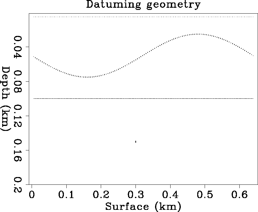
As in the previous example, a scatterer is located at (z=0.15, y=0.32)
in a constant velocity
v=1 medium. And there is a supposedly irregular earth surface that
can be expressed as the function iz = 10 + 5 sin( 2.*3.14*2* iy/ny).
The maximum elevation difference is 50 m. The datuming geometry is
shown in Figure 3.
This kind of geometry is not unusual in land seismic surveys such as those of
the mountainous regions in southwest China.
The indices iz, iy are the depth and horizontal grid indices.
I have chosen this particular surface for the sake of convenience.
Any irregular surface can be used, as long as every boundary grid point
as defined by the boundary has a recorded trace.
No gaps can exist on the boundary grid.
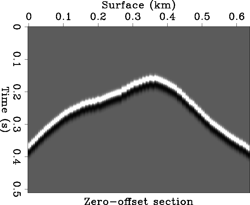
I generate the synthetic zero-offset section in Figure 4
at the irregular datum by ray tracing.
The diffraction time curve deviates greatly from a perfect hyperbola
because of the irregular recording surface.
Datum2.H
Figure 3 The datuming geometry
of Figures 4, 5, and 6.
The point S represents the position of the scatterer.
The asterisk curve represents the field recording datum.
The dotted and dashed lines
represent the new datums for upward and downward datuming.
|
|  |


d2
Figure 4 The wavefields recorded
at the irregular surface datum.
|
|  |


Then I use a grid with
nz=20, ny=128, dz=0.005, dy=0.005, and dt=0.001 to run the
two-way wave equation forward in time,
with the synthetic record as the boundary condition
at the irregular recording surface,
which is located inside the computational rectangle.
The top and the two sides of the rectangle
are designed as absorbing boundaries. The bottom boundary can be assigned
any condition because it does not affect the computation.
The desired wavefields at the new datum surface
are the absorbing history wavefields at the top iz=1 of the grid.
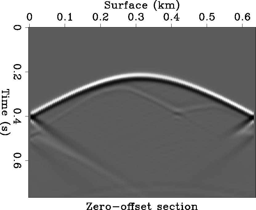
The results are shown in Figure 5.
The datuming is done by an average of 50 m.
Now the diffraction time curve has been
restored to a hyperbola, and
the apex of the hyperbola is
at time t=0.2, and lateral position y=0.32.
Boundary reflection effects appear at the two sides,
because in datuming to a higher datum the wave incidence angle upon
the two sides increases, and the effects of absorbing boundary conditions
(Clayton and Engquist, 1977) at large incidence angles are not
as good as those at small incidence angles.
By upward datuming to a planar datum whose
elevation equals that of the highest point of the irregular topography,
the edge reflection can be decreased.
The other way to deal with boundary reflections is
to pad with zeroed traces beyond the edge as placeholders for the energy that
migrates out of the original grid during the datuming extrapolation process
(Berryhill, 1984).
There is a light ghost following the main hyperbola, which looks like
the lateral reverse of the original diffraction curve.
The ghost reflection results from the reverberations at the input datum.
The ghost can be removed by implementing the recorded wavefields
as a series of point sources instead of simple boundary conditions.
d2.up
Figure 5 The extrapolated wavefields
at an upper planar datum.
|
|  |


Next: Datuming from an irregular
Up: POSTSTACK DATUMING
Previous: Datuming from a planar
Stanford Exploration Project
11/17/1997


