

Next: CONCLUSIONS
Up: NUMERICAL RESULTS
Previous: Accuracy
I use the local ray-tracing method to compute the traveltime field
in a two-layer velocity model. The velocities are 1.5 km/s
in the top layer and 4.5 km/s in the bottom layer. After the
critical angle, each point in the top layer has two arrivals:
an arrival propagating directly from the source and an arrival
refracted at the boundary of two layers.
Therefore, the traveltime field is multi-valued in this region.
I compute the traveltime field of multiple arrivals by
applying the local ray-tracing method with three different
selections: the first one selects the first arrivals, the second
one selects the most energetic arrivals, and the third one selects
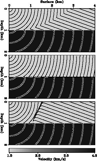
upgoing arrivals. Figure ![[*]](http://sepwww.stanford.edu/latex2html/cross_ref_motif.gif) shows the contours of the
three single-valued traveltime field. In the top layer, the first
arrivals are the combinations of direct arrivals and diffracted arrivals,
the most energetic arrivals are purely direct arrivals, and the upgoing
arrivals have more diffracted arrivals than the first arrivals.
Three traveltime fields are identical in the bottom layer because
each point there has only one arrival.
The discontinuities of the contours are easy to identify.
Figure
shows the contours of the
three single-valued traveltime field. In the top layer, the first
arrivals are the combinations of direct arrivals and diffracted arrivals,
the most energetic arrivals are purely direct arrivals, and the upgoing
arrivals have more diffracted arrivals than the first arrivals.
Three traveltime fields are identical in the bottom layer because
each point there has only one arrival.
The discontinuities of the contours are easy to identify.
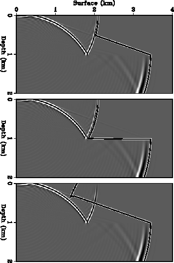
Figure ![[*]](http://sepwww.stanford.edu/latex2html/cross_ref_motif.gif) compares these results calculated by the local
ray-tracing method with the wave field simulated by wave-equation modeling.
Because a minimum phase wavelet is used in wave-equation modeling,
the contour lines of the traveltime fields closely follow the first
breaks of the wavelets in the corresponding
snapshots of the wave fields.
compares these results calculated by the local
ray-tracing method with the wave field simulated by wave-equation modeling.
Because a minimum phase wavelet is used in wave-equation modeling,
the contour lines of the traveltime fields closely follow the first
breaks of the wavelets in the corresponding
snapshots of the wave fields.
ttmlay
Figure 16 A point source positioned at the upper-left corner of the model
generates a multi-valued traveltime field in a two-layer velocity model.
This field is disassembled into three single-valued
traveltime fields corresponding
to first arrivals (top), most energetic arrivals (middle)
and upgoing arrivals (bottom).
The contour lines of three single-valued traveltime fields are plotted on
the intensity backgrounds showing the velocity field.
The contour interval is 0.1 second.
 wavelay
Figure 17 Comparison of the wave field simulated by wave-equation modeling
with the traveltime fields calculated by the local ray-tracing method.
The point source is positioned at the upper-left corner of the model.
The intensity plots in three panels show a common snapshot of the wave
field at 1.4 second; the overlain curves are the 1.4s-contour lines of
three single-valued traveltime fields (see Figure ![[*]](http://sepwww.stanford.edu/latex2html/cross_ref_motif.gif) ).
).

As a final experiment, I compute the traveltime field in the Marmousi
model shown in Figure ![[*]](http://sepwww.stanford.edu/latex2html/cross_ref_motif.gif) . This synthetic velocity model has
a complex geological structure with large velocity contrasts.
Many regions in the model have multiple arrivals.
The computation is conducted on a triangular grid with a grid size of 16 meters.
Figure
. This synthetic velocity model has
a complex geological structure with large velocity contrasts.
Many regions in the model have multiple arrivals.
The computation is conducted on a triangular grid with a grid size of 16 meters.
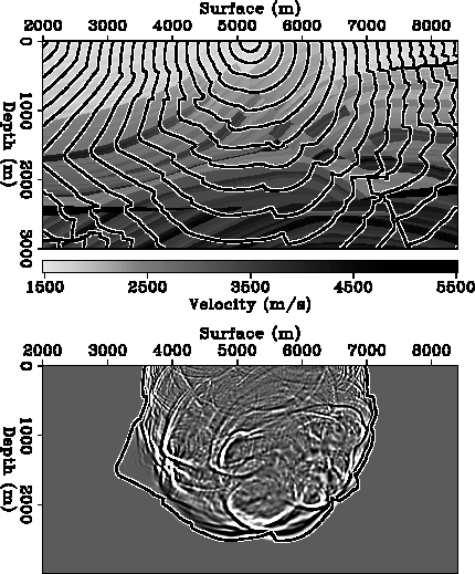
Figure ![[*]](http://sepwww.stanford.edu/latex2html/cross_ref_motif.gif) shows the traveltime field of first arrivals in
the Marmousi model. From the contour plot, we see that the circular
wavefronts generated at the source point are severely distorted after
propagate through the complex structure. The wavefronts propagate
rapidly in the thin layers of high interval velocities.
The comparison with the wave field computed by wave-equation modeling
confirms accurate result of the local ray-tracing method.
This experiment also shows that the local ray-tracing method is robust.
shows the traveltime field of first arrivals in
the Marmousi model. From the contour plot, we see that the circular
wavefronts generated at the source point are severely distorted after
propagate through the complex structure. The wavefronts propagate
rapidly in the thin layers of high interval velocities.
The comparison with the wave field computed by wave-equation modeling
confirms accurate result of the local ray-tracing method.
This experiment also shows that the local ray-tracing method is robust.
Figure ![[*]](http://sepwww.stanford.edu/latex2html/cross_ref_motif.gif) shows that the first arrivals at some regions
are considerably weaker than later arrivals. Therefore, I compute
another traveltime field by selecting most energetic arrivals.
As shown in Figure
shows that the first arrivals at some regions
are considerably weaker than later arrivals. Therefore, I compute
another traveltime field by selecting most energetic arrivals.
As shown in Figure![[*]](http://sepwww.stanford.edu/latex2html/cross_ref_motif.gif) , the result on this model is not completely
satisfactory. Although energetic arrivals at the shallow regions of the
model are correctly computed,
the method still picks up the weak arrivals diffracted at the
boundaries of high-velocity thin layers.
An explanation of this result is that the local ray-tracing method
does not ensure global selections. The weak arrival propagating in
the high-velocity thin layer may be strong at the early stage of the
propagation.
, the result on this model is not completely
satisfactory. Although energetic arrivals at the shallow regions of the
model are correctly computed,
the method still picks up the weak arrivals diffracted at the
boundaries of high-velocity thin layers.
An explanation of this result is that the local ray-tracing method
does not ensure global selections. The weak arrival propagating in
the high-velocity thin layer may be strong at the early stage of the
propagation.
twmar1
Figure 18 The traveltime field of first arrivals in the Marmousi velocity model.
The point source is positioned at the top center of the model.
The top panel displays the velocity field. Overlain are the contour lines
of the traveltime field with 0.1 second intervals.
The bottom panel compares the wave field computed by wave-equation modeling
with the traveltime field calculated by the local ray-tracing method.
The intensity plot shows a snapshot of the wave field at 1. second;
the overlain curve is the 1.s-contour line of the traveltime field.
 twmar2
Figure 19 The traveltime field of most energetic arrivals in the Marmousi velocity model.
The point source is positioned at the top center of the model.
The top panel displays the velocity field. Overlain are the contour lines
of the traveltime field with 0.1 second intervals.
The bottom panel compares the wave field computed by wave-equation modeling
with the traveltime field calculated by the local ray-tracing method.
The intensity plot shows a snapshot of the wave field at 1. second;
the overlain curve is the 1.s-contour line of the traveltime field.


Next: CONCLUSIONS
Up: NUMERICAL RESULTS
Previous: Accuracy
Stanford Exploration Project
11/17/1997
![[*]](http://sepwww.stanford.edu/latex2html/cross_ref_motif.gif) shows the contours of the
three single-valued traveltime field. In the top layer, the first
arrivals are the combinations of direct arrivals and diffracted arrivals,
the most energetic arrivals are purely direct arrivals, and the upgoing
arrivals have more diffracted arrivals than the first arrivals.
Three traveltime fields are identical in the bottom layer because
each point there has only one arrival.
The discontinuities of the contours are easy to identify.
Figure
shows the contours of the
three single-valued traveltime field. In the top layer, the first
arrivals are the combinations of direct arrivals and diffracted arrivals,
the most energetic arrivals are purely direct arrivals, and the upgoing
arrivals have more diffracted arrivals than the first arrivals.
Three traveltime fields are identical in the bottom layer because
each point there has only one arrival.
The discontinuities of the contours are easy to identify.
Figure ![[*]](http://sepwww.stanford.edu/latex2html/cross_ref_motif.gif) compares these results calculated by the local
ray-tracing method with the wave field simulated by wave-equation modeling.
Because a minimum phase wavelet is used in wave-equation modeling,
the contour lines of the traveltime fields closely follow the first
breaks of the wavelets in the corresponding
snapshots of the wave fields.
compares these results calculated by the local
ray-tracing method with the wave field simulated by wave-equation modeling.
Because a minimum phase wavelet is used in wave-equation modeling,
the contour lines of the traveltime fields closely follow the first
breaks of the wavelets in the corresponding
snapshots of the wave fields.


