|
synmdl
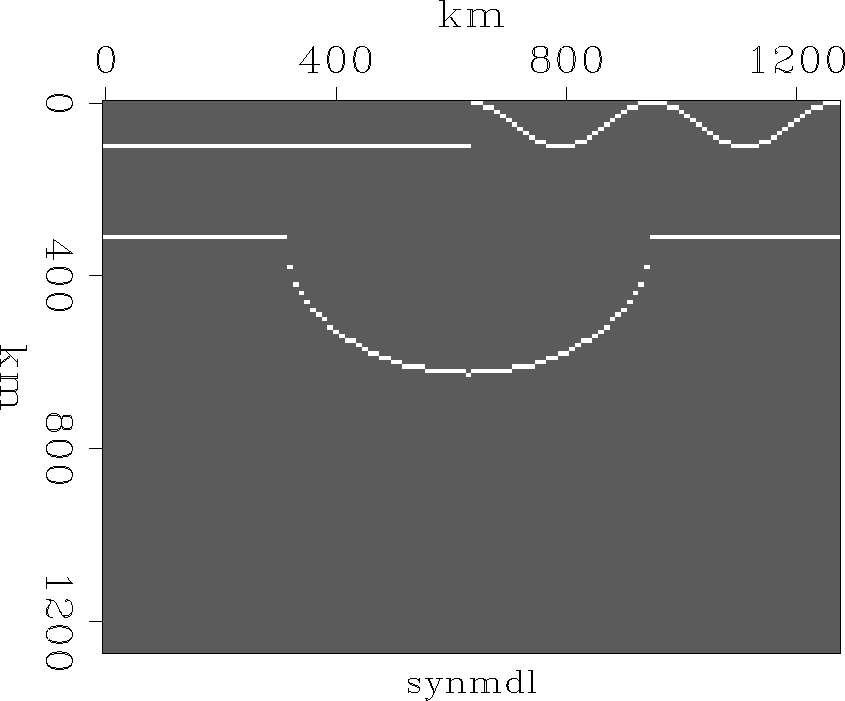
Figure 5 Synthetic model with a syncline reflector image (lower) under an undulating surface (upper). |  |
![[*]](http://sepwww.stanford.edu/latex2html/cross_ref_motif.gif) contains a simple model consisting
of a syncline reflector under an undulating surface.
The modeling experiment was done
using the algorithm explained in Figure
contains a simple model consisting
of a syncline reflector under an undulating surface.
The modeling experiment was done
using the algorithm explained in Figure ![[*]](http://sepwww.stanford.edu/latex2html/cross_ref_motif.gif) for a constant velocity
and the result is shown in Figure
for a constant velocity
and the result is shown in Figure ![[*]](http://sepwww.stanford.edu/latex2html/cross_ref_motif.gif) (b).
During the modeling, we save a wavefield at the bottom
of the topography (Figure
(b).
During the modeling, we save a wavefield at the bottom
of the topography (Figure ![[*]](http://sepwww.stanford.edu/latex2html/cross_ref_motif.gif) (a)).
Comparing these two wavefields, we can see the effect
of the irregular topography,
the wavefield has a big discontinuity at the center
and fluctuates on the right half because of the surface topography.
Migration was performed using
the algorithm shown in Figure
(a)).
Comparing these two wavefields, we can see the effect
of the irregular topography,
the wavefield has a big discontinuity at the center
and fluctuates on the right half because of the surface topography.
Migration was performed using
the algorithm shown in Figure ![[*]](http://sepwww.stanford.edu/latex2html/cross_ref_motif.gif) and the results are shown in Figure
and the results are shown in Figure ![[*]](http://sepwww.stanford.edu/latex2html/cross_ref_motif.gif) (d).
We can see that the syncline reflector is correctly imaged,
but there is background noise.
During the migration, we saved a wavefield at the bottom
of the topography and it is shown
in the Figure
(d).
We can see that the syncline reflector is correctly imaged,
but there is background noise.
During the migration, we saved a wavefield at the bottom
of the topography and it is shown
in the Figure ![[*]](http://sepwww.stanford.edu/latex2html/cross_ref_motif.gif) (c).
This Figure shows artifacts due to inaccuracies in the
extrapolation algorithm.
The noise comes mainly from the inaccuracies of the modeling
and the next section presents an improved scheme
which simulates nature more closely.
(c).
This Figure shows artifacts due to inaccuracies in the
extrapolation algorithm.
The noise comes mainly from the inaccuracies of the modeling
and the next section presents an improved scheme
which simulates nature more closely.
|
synmdl
Figure 5 Synthetic model with a syncline reflector image (lower) under an undulating surface (upper). |  |
 |
![[*]](http://sepwww.stanford.edu/latex2html/cross_ref_motif.gif) (b).
(b).