 |
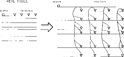
Figure 1 A reflection seismic experiment in a plane-layered earth and its equivalent multiple-free "listening reflector model."
![[*]](http://sepwww.stanford.edu/latex2html/cross_ref_motif.gif) ).
In addition, each receiver would have an ``angular sensitivity" (radiation
pattern) equal to the angle-dependent reflectivity of the interface below it.
By analogy to the ``exploding reflector model," we could name
it the ``listening reflector model".
).
In addition, each receiver would have an ``angular sensitivity" (radiation
pattern) equal to the angle-dependent reflectivity of the interface below it.
By analogy to the ``exploding reflector model," we could name
it the ``listening reflector model".
 |
With this model in mind, it is possible to devise an interval velocity scheme in which we upward continue the receivers with different velocities, and compare the results with the original data. The correct velocity of a given interval will be the one that minimizes the phase difference between the reflectors at the top of the interval before and after the continuation. Once the average interval velocities were determined, one could refine the estimation (solve the dynamics) using the amplitude ratios before and after the continuation.
 |
Claerbout (1978) derived an interval velocity estimation scheme
that, although formulated in a different way, is closely related
to this principle.
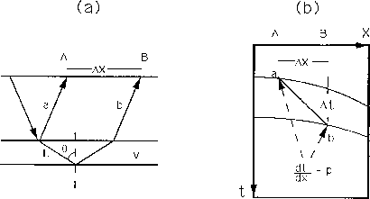
His formulation is based on the analytical relation involving the
interval velocity between two adjacent reflectors, the
temporal and spatial coordinates of points in the two
wavefronts that share the same horizontal slowness, and
the horizontal slowness.
The derivation of the basic equation from Figure ![[*]](http://sepwww.stanford.edu/latex2html/cross_ref_motif.gif) is straightforward:
is straightforward:
![]()
| |
(1) |
Using equation (1) as the underlying principle, Gonzalez and Claerbout (1979) derived a wave-equation-based velocity estimation method. Deregowski (1979) used the same equation to develop a tangency-picking scheme to perform interval velocity analysis. Both methods were implemented in the framework of the retarded Snell midpoint coordinates.
Equation (1) represents a direct link between the interval velocity and some measurable attributes of the data. In contrast to indirect interval velocity estimation methods, which are based either on ray-tracing or on the initial fitting of the stacking spectrum, direct methods do not have a cumulative increase of error with depth.
The next two sections describe two different velocity estimation schemes that are also based in equation (1). The first uses an automatic-picking process developed by Zhang and Claerbout (1990) and improved by Zhang (1991) to select the reflection events and compute the horizontal slownesses. The other is based on the same picking process but uses beam-stacks (Biondi, 1990) to provide a probability distribution for the horizontal slownesses.