


Diffraction tomography is based on the ``Diffraction Slice Theorem'':
The Fourier transform of the field scattered by a weak scatterer which was registered on a plane perpendicular to the normal vector of the wavefronts leads to values of the 2-D Fourier transform of the object function along halfcircles with the radius k.The theorem can be derived as follows (Langenberg, K.L., 1986): Write the Porter-Bojarski integral as a volume integral and perform a two-dimensional spatial Fourier transform to the kx-ky-space. Now assume weak scattering and take the wavefield on a registration plane z=const. The Born and Rytov approximations are most common to introduce the idea of weak scatterers. Both linearize the integral equations to be solved while assuming the displacement (Born), respectively the gradient of the displacement (Rytov) due to scattering, to be small. Small-scale heterogeneties can be best imaged by the Born approximation whereas to image large-scale heterogeneties it is better to use the Rytov approximation (Pratt, R.G., 1989).
With the above derivation in mind, it is obvious that the diffraction slice theorem is the weak scatterer equivalent to the Raleigh integrals. Diffraction tomography is the weak scatterer form of Raleigh Sommerfeld Holography with angular diversity. Although an extension of diffraction tomography to the elastic case is possible, it has not yet been done.
The old-Greek word ``tomé'' means ``slice'', and therefore we can translate ``tomography'' with ``imaging by slices (through the object function).'' The slices to be superposed are essentially the intersections of the object function and the Ewald halfcircles. Because we allow weak inhomogeneties, small areas around the intersections can be included in the superposition (Woodward, M.J., and Rocca, F., 1989). In practice, there is no significant difference. This has been shown by Menges and Wenzel (1990) for migration.
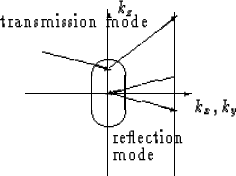 |
It is important to distinguish between transmission and reflection
mode. Transmission mode means that the difference between the angle of
incidence and the reflection angle, respectively diffraction angle, is small for
the recorded scattered wavefield. The absolute
value of this angle should be between
and ![]() .We speak of reflection mode
if the absolute value of the difference
between both angles is between
.We speak of reflection mode
if the absolute value of the difference
between both angles is between
![]() and
and ![]() .Zero offset migration performs the backpropagation of reflection mode data
measured under a difference angle of
.Zero offset migration performs the backpropagation of reflection mode data
measured under a difference angle of ![]() and uses the one-way wave equation,
or a transmission mode theory.
In case of transmission mode or reflection mode, only the
halfcircle of the Ewald sphere
closed towards the registration plane and its closest surroundings
can be reconstructed because we register only the energy
scattered towards the receivers. One conclusion is that an optimal
image can only be obtained if the scatterer is
completely surrounded by receivers. In addition, the signal must be
broad-banded.
and uses the one-way wave equation,
or a transmission mode theory.
In case of transmission mode or reflection mode, only the
halfcircle of the Ewald sphere
closed towards the registration plane and its closest surroundings
can be reconstructed because we register only the energy
scattered towards the receivers. One conclusion is that an optimal
image can only be obtained if the scatterer is
completely surrounded by receivers. In addition, the signal must be
broad-banded.
If we superpose reflection mode diffraction tomography images for different frequencies, we perform a prestack weak scatterer migration, i.e., a weak scatterer frequency and angular diversity Raleigh Sommerfeld Holography. Constant offset migration is the reflection mode of diffraction tomography with frequency but not angular diversity, if we assume weak scatterers.
If the signal frequency, i.e., the wavenumber k, approaches infinity, the Ewald halfcircles have infinite radius and can locally be approximated by straight lines. The diffraction slice theorem simplifies to the Fourier slice theorem:
Straight lines through the object function (i.e., plane waves registered under a certain angle)correspond to straight lines through the two-dimensional Fourier transform of the object function with the same angle
The larger the object to be mapped, the sooner the approximation of
halfcircles by lines is valid.
For ![]() (with the
scatterer length a) bended rays are getting straight rays and
diffraction tomography simplifies to travel-time tomography. Instead of a
backpropagation based on the wave equation, it is sufficient to perform
a backprojection based on the inverse Radon transform. Straight cuts
through the object function are the slices to be superposed.
(with the
scatterer length a) bended rays are getting straight rays and
diffraction tomography simplifies to travel-time tomography. Instead of a
backpropagation based on the wave equation, it is sufficient to perform
a backprojection based on the inverse Radon transform. Straight cuts
through the object function are the slices to be superposed.
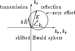 |
Langenberg (1986) and Mora (1989) showed that the spatial resolution for the transmission
and reflection modes are different.
For an incident wave of constant frequency, the wave vector ![]() is smaller for transmitted waves than for
reflected waves. The smaller the offset between source and receiver the more
the wave vectors of the backscattered wavefield
and the negative of the incident wave vector to point in the same direction. Their sum
has its maximum at zero offset.
is smaller for transmitted waves than for
reflected waves. The smaller the offset between source and receiver the more
the wave vectors of the backscattered wavefield
and the negative of the incident wave vector to point in the same direction. Their sum
has its maximum at zero offset.
Since reflection mode data covers better the higher spatial frequencies than the transmission data, it has higher spatial resolution. The resolution maximum is at zero offset. (Transmission) tomography is the better tool to image big structures because it covers better the low wavenumber areas. Of course these comparisons are only valid if the reflected and transmitted data have the same frequencies. In practice, this will rarely be the case. Cross-hole tomography registrations with frequencies of some thousand Hertz usually lead to a much better spatial resolution than surface data migration with frequencies of two orders lower.