|
|
|
|
Reverse-time migration using wavefield decomposition |
Strong RTM artifacts result from the undesired cross-correlations of head waves, diving waves, and backscattered waves (Yoon and Marfurt, 2006; Yoon et al., 2004). These artifacts are strong when high velocity contrasts are present, especially in the shallow regions. In addition, undesired artifacts caused by SRMs can also confuse the interpretation.
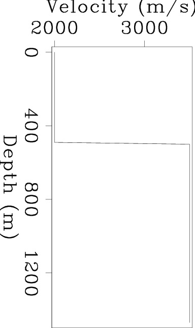
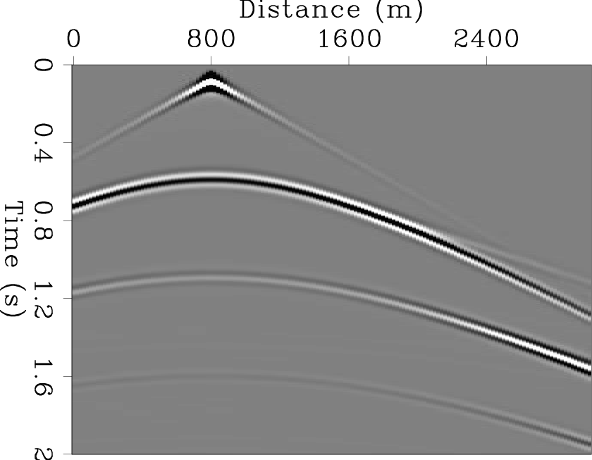
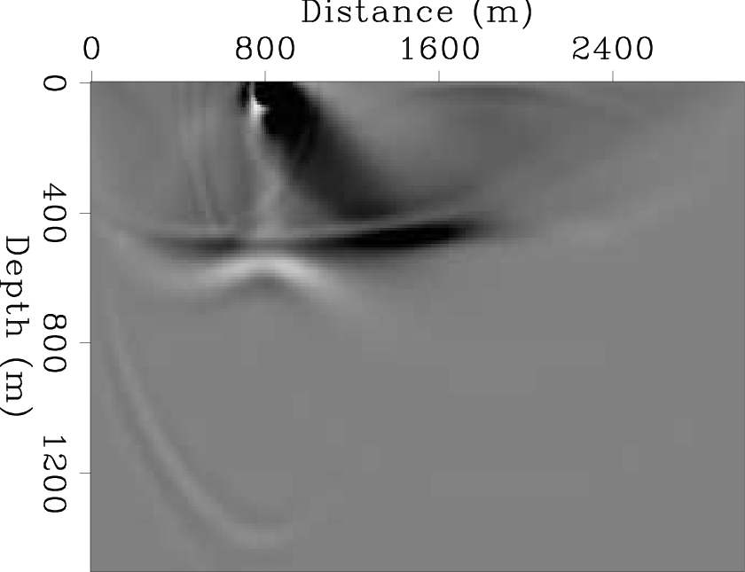
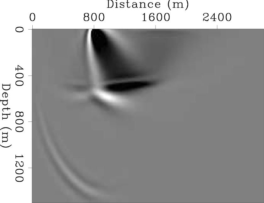
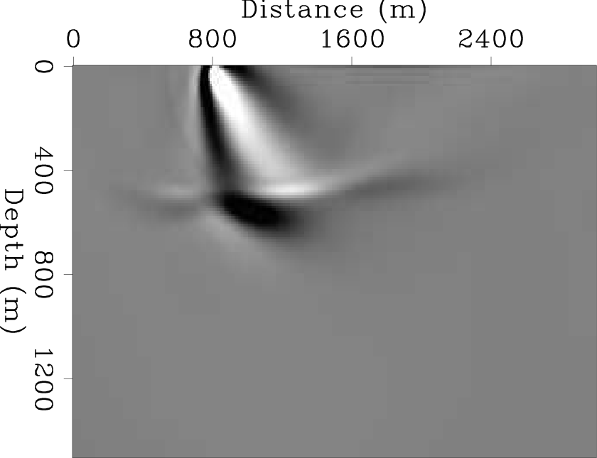
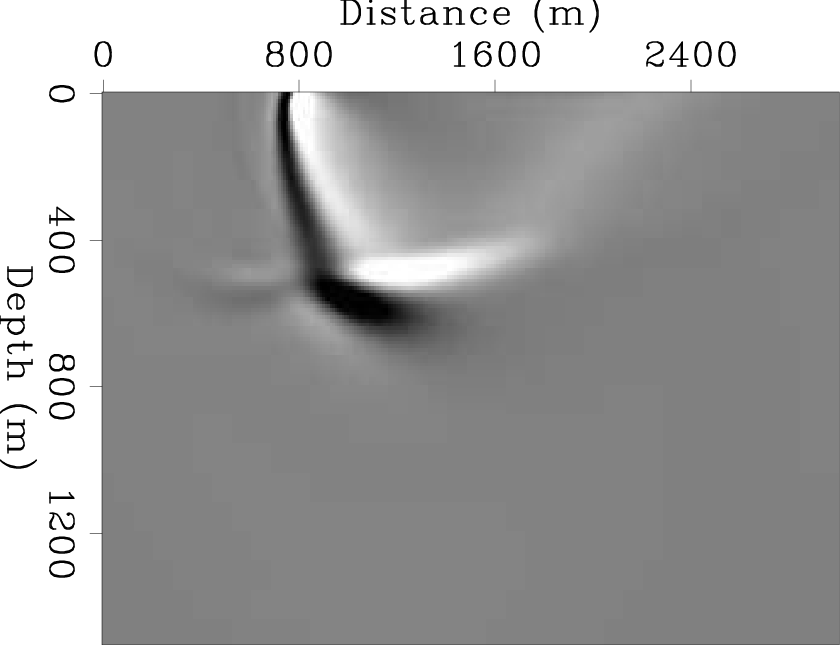
Figure 2(a) shows a simple 1-D velocity model consisting of a strong velocity contrast, whereas Figure 2(b) is a shot profile corresponding to this velocity model. Figure 3(a) shows the conventional RTM image from this shot profile using the true interval velocity as the migration velocity. The figure contains many artifacts due to head waves, diving waves, and backscattered waves at shallow depths. In addition, there are also artifacts due to SRMs at the bottom of the figure. Muting the head waves, diving waves, and direct waves before RTM can suppress the corresponding artifacts as shown in Figure 3(b). In practice, the artifacts due to SRMs can be removed by using an appropriate SRM elimination program. Here, the synthetic data without SRM are generated by applying a nonflecting top boundary to wavefield extrapolation. Figure 4(b) shows the RTM image from the muted shot profile without SRM shown in Figure 4(a). Although artifacts due to head waves, diving waves, and SRM have been removed, the adverse effect of backscattered waves still remains above the strong reflector (Figure 4(b)). Thus, only RTM artifacts due to backscattered waves cannot easily be suppressed by pre-migration processing.
|
|---|
|
vel0,data0-srm
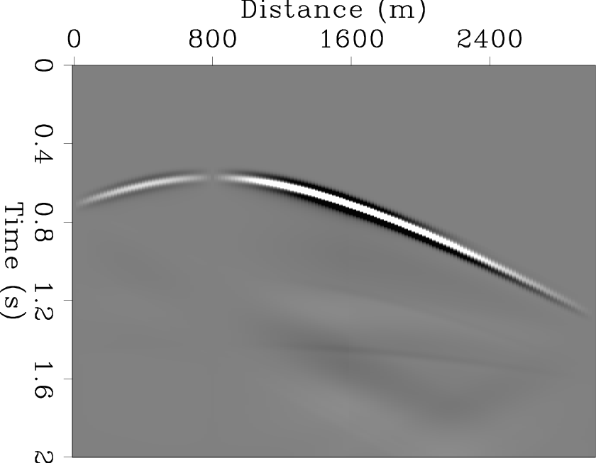
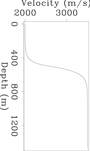
Figure 2. (a) 1-D true interval velocity model. (b) Synthetic shot profile from an explosive source on the surface in the velocity model (a). |
|
|
|
|---|
|
rtm-sharpv0-srm,rtm-sharpv0-srm-muted
Figure 3. RTM images from the shot profile in Figure 2(b) before (a) and after (b) muting the head waves and diving waves. The true interval velocity shown in Figure 2(a) has been used as the migration velocity for both images. |
|
|
|
|---|
|
data0-nosrm,rtm-sharpv0-muted-nosrm
Figure 4. (a) A shot profile without SRM after muting the head waves and diving waves; weighting and tapering are also applied. (b) An RTM image from this shot profile; the true interval velocity shown in Figure 2(a) has been used as the migration velocity. |
|
|
Robein (2010) summarized four main approaches that have been used to suppress RTM artifacts due to backscattered waves: 1) smoothing the velocity model, 2) applying an appropriate filter to the post-migration image, 3) using nonreflecting wave propagation with directional damping, and 4) modifying the imaging condition.
Smoothing strong velocity contrasts can reduce the amplitude of undesired reflected waves; however, this can bias the accuracy of imaging due to incorrect velocity models. Figure 5(b) shows the same RTM image as Figure 4(b), but using the smoothed migration velocity shown in Figure 5(a). As shown in Figure 5(b), velocity smoothing can partly reduce the artifacts caused by backscattered waves; however, the artifacts still have an adverse effect on the shallow parts of the image. Although velocity smoothing can also cause other kinds of artifacts (Fei et al., 2010), this approach is currently used due to its robustness and low computational cost.
|
|---|
|
vel0-mig,rtm-v0-nosrm-muted
Figure 5. The effects of velocity smoothing on the RTM image. (a) Smoothed migration velocity corresponding to the true interval velocity in Figure 2(a). (b) RTM image from muted data without SRM using this smoothed migration velocity (a). |
|
|
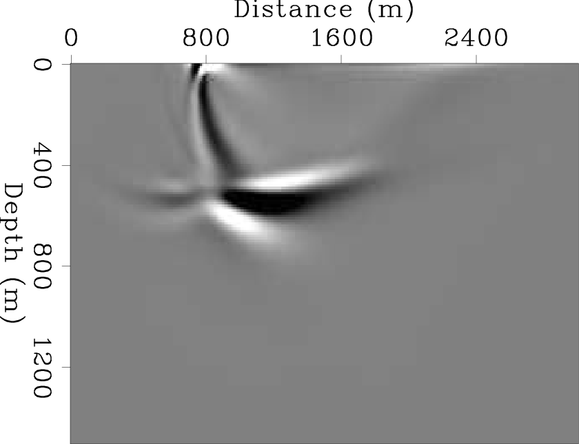
There are many post-migration approaches whereby RTM artifacts are filtered after imaging. Low-cut filtering is an approach that can highly attenuate RTM artifacts as shown in Figure 6, where a causal low-cut filter was used. However, there still remains some noise in the figure. Moreover, low-cut filters can reduce the amplitude of steeply dipping reflectors, which mainly contain low-frequency information. Guitton et al. (2006) presented another possible post-migration solution by applying a least-squares filter to RTM images. In addition, the application of a Laplacian filter with appropriate pre- and post-migration processing is an effective solution that can remove RTM artifacts without hurting steeply dipping reflectors (Zhang and Sun, 2009).
|
rtm-v0-nosrm-muted-lowcut
Figure 6. The RTM image in Figure 5(b) after applying a causal low-cut filter. |
|
|---|---|
|
|
Applying a directional damping term to the wave equation can suppress unwanted internal reflections, including backscattered waves (Fletcher et al., 2006). This approach is more effective than velocity smoothing, since it does not alter the migration velocity. However, picking the problematic interfaces, which cause artifacts due to backscattered energy, is required in order to obtain directional damping coefficients. Therefore, the approach using directional damping is time consuming.
Modifying the imaging condition in RTM is another solution. This generally provides more effective noise attenuation than the other methods discussed above. The ultimate goal of this approach is to keep only energy along reflectors in the final image. There are various techniques used for modifying the imaging condition. The results of using different imaging conditions were discussed by Valenciano and Biondi (2003), Yoon et al. (2004), Liu et al. (2007), and Chattopadhyay and McMechan (2008).
RTM using wavefield decomposition is a method based on the modification of the imaging condition. This method modifies the imaging condition using wavefield decomposition in the Fourier domain, and was first introduced by Liu et al. (2007). This technique solves the problem of artifacts by suppressing their formation in the RTM algorithm. To demonstrate why this technique is worth investigation, we first need to understand the origin of RTM artifacts.
|
|
|
|
Reverse-time migration using wavefield decomposition |