|
|
|
|
Seismic reservoir monitoring with encoded permanent seismic arrays |
 is frequency,
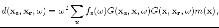
 is given by
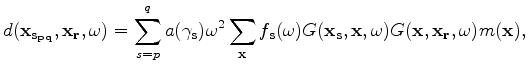
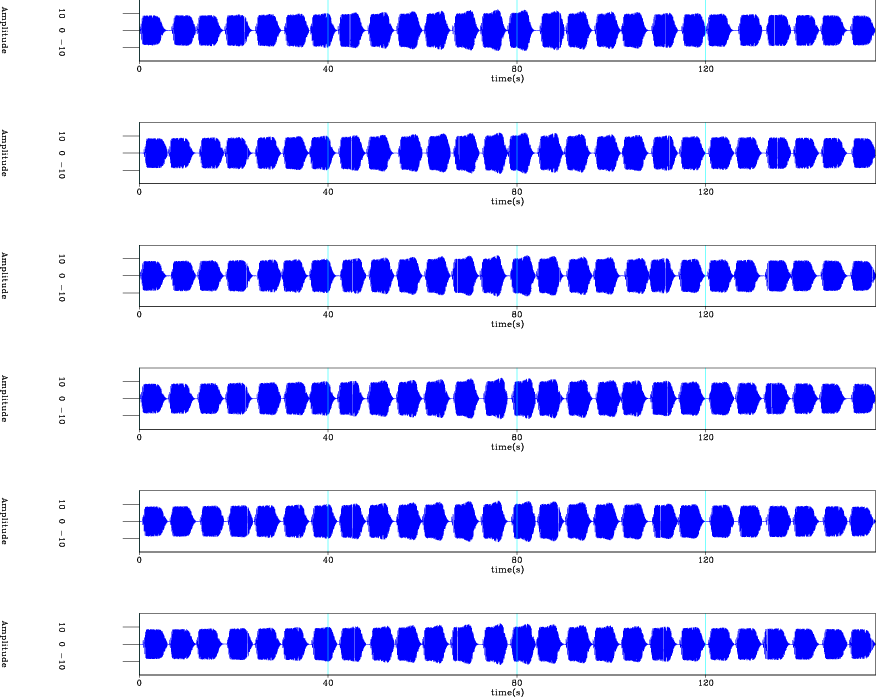
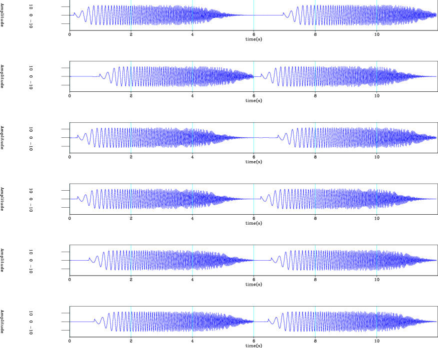
Randomized intermittent shooting of several shots is equivalent to repetition of equation 2 with a spatially and temporally varying encoding function. The recorded data are similar to passive data, except that all shot positions and timings are known. Therefore, the recording experiment can be regarded as a controlled-source continuous-recording experiment. Figures 1 and 2 show examples of idealized source waveforms at six shot positions. It is assumed that these sources are orders of magnitude weaker than conventional seismic sources and that data from a single sweep is insufficient to create a good-quality image.
|
|---|
|
perm-src
Figure 1. First |
|
|
|
|---|
|
perm-src-
Figure 2. First |
|
|
Direct imaging of the recorded data, the adjoint to equation 2, is a linear phase-encoding migration operator (Romero et al., 2000). This is equivalent to a single shot-profile migration of the recorded data with an areal source-function derived by concatenating delayed source waveforms from all shot positions.
|
|
|
|
Seismic reservoir monitoring with encoded permanent seismic arrays |