|
|
|
|
Reverse Time Migration of up and down going signal for ocean bottom data |
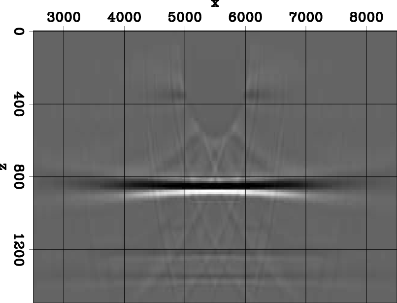
In our RTM scheme, we perform migration by injecting over-under data into the finite difference grid. Figure 5(a) shows the resulting reflectivity after injecting the over signal at 480m depth and under signal at 500 m depth. As expected from the original velocity model displayed in Figure 4(a), there is a reflector below the 800 m depth. In addition, there are also two weaker coherent artifacts at 1200 m and 1300 m depth.
|
|---|
|
ou0,ou1,ou2
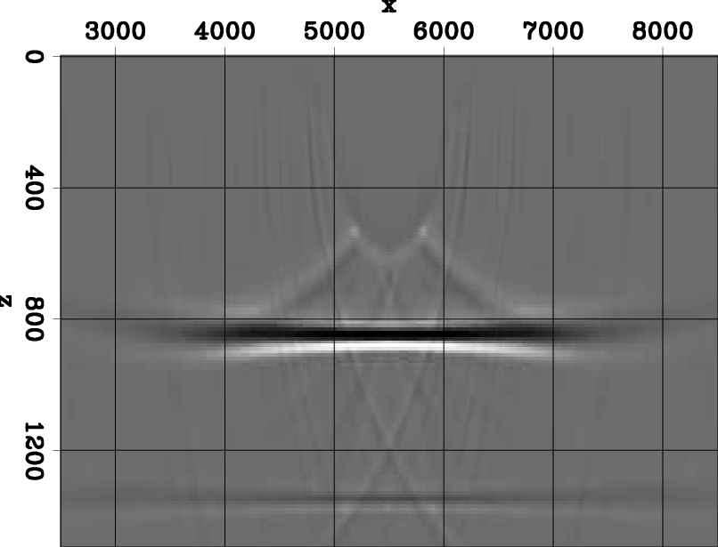
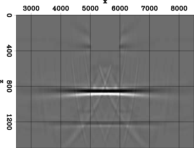
Figure 5. (a) The migration result using the over-under data. There is a reflector below the 800 m depth. In addition, there are also two weaker coherent artifacts at 1200 m and 1300 m depth. (b) The migration result of over-under with up-going only energy; (c) the migration result of over-under data with down-going only energy. [CR] |
|
|
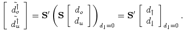
We also migrate with only the up-going and only the down-going signal. This can be accomplished using the adjoint of the up-down separation operator ![]() and zeroing the appropriate data component in the up-down space. Let
and zeroing the appropriate data component in the up-down space. Let ![]() and
and ![]() be the over and under data synthesized as described in the last section. To filter out the down-going energy in
be the over and under data synthesized as described in the last section. To filter out the down-going energy in ![]() and
and ![]() , we can zero the down-going data in the up-down data space before applying the adjoint separation operator
, we can zero the down-going data in the up-down data space before applying the adjoint separation operator ![]() as shown below:
as shown below:
Note that the resulting data
 and
and
![]() are still in the over-under data space but contain only up-going energy. Similarly, to filter out the up-going energy in
are still in the over-under data space but contain only up-going energy. Similarly, to filter out the up-going energy in ![]() and
and ![]() , we can use:
, we can use:
The results of performing RTM with only the down-energy and only the up-energy are shown in Figure 5(b) and Figure 5(c) respectively. Both figures have the same clip. In Figure 5(b), the reflector at 800 m is much wider than the corresponding one in Figure 5(c). This is because migrating with down-going energy is primarily imaging with the receiver ghost signal. On the other hand, migrating with up-going energy is primarily imaging with the primary signal. Imaging with the receiver ghost data provides a wider subsurface illumination, because its point of reflection is further away from the receiver than that of the primary reflection. Another observation is that the amplitude of the 800 m reflector in figure 5(c) is stronger than the amplitude in Figure 5(b). The primary signal has stronger amplitude than any signal of higher order (ghost or multiples) because of geometric spreading. Therefore, imaging with the primary gives a higher-amplitude reflectivity model than imaging with the receiver ghost.
|
|
|
|
Reverse Time Migration of up and down going signal for ocean bottom data |