 |
 |
 |
 | Angle domain common image gathers for steep reflectors |  |
![[pdf]](icons/pdf.png) |
Next: Numerical examples
Up: Shan and Biondi: Angle
Previous: Angle domain CIGs by
Reverse-time migration solves the two issues in downward continuation migration in generating CIGs for steep reflectors,
but it is well known that it is expensive to apply reverse-time routinely.
Plane-wave migration in tilted coordinates has been demonstrated useful imaging technology for steep reflectors (Shan and Biondi, 2004; Shan et al., 2007).
In plane-wave migration in tilted coordinates, the propagation direction of the waves illuminating steeply dipping reflectors is usually close to the extrapolation direction and thus they can be imaged correctly.
In this section, we discuss how to generate angle domain CIGs by plane-wave migration in tilted coordinates and show that
it can also produce reliable CIGs for steep reflectors. We start with CIGs in the conventional plane-wave migration.
As with shot-profile migration, offset domain CIGs in plane-wave migration are formed as follows:
 |
(9) |
where  is the horizontal subsurface offset,
 and
and
 are the source and receiver wavefields corresponding to the ray parameter
  , respectively.
Notice that the imaging condition in equation 9 is the cross-correlation between the source and receiver wavefields weighted with the angular frequency
, respectively.
Notice that the imaging condition in equation 9 is the cross-correlation between the source and receiver wavefields weighted with the angular frequency  , which is also called
  -filter in Radon transform literature.
As with the conventional zero-subsurface-offset image, offset domain CIGs defined in equation 9 are equivalent to those obtained by shot-profile migration.
Offset domain CIGs are transformed to angle domain CIGs by local slant-stacking (equation 2).
-filter in Radon transform literature.
As with the conventional zero-subsurface-offset image, offset domain CIGs defined in equation 9 are equivalent to those obtained by shot-profile migration.
Offset domain CIGs are transformed to angle domain CIGs by local slant-stacking (equation 2).

|
|---|
bpvel
Figure 1. Velocity model of the BP velocity Benchmark.
|
|---|
![[png]](icons/viewmag.png)
|
|---|

|
|---|
imagetilt
Figure 2. Image obtained by plane-wave migration in tilted coordinates. Both steep salt flank and near-flat sediments are present in this area.
|
|---|
|
|
|---|
Given a plane-wave source corresponding to the ray parameter , we use the tilted coordinates
 with a tilting angle
  .
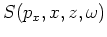
The subsurface offset domain CIGs for this plane-wave source are formed by:
.
The subsurface offset domain CIGs for this plane-wave source are formed by:
 |
(10) |
where the subsurface offset  parallels the
  axis.
In plane-wave migration in tilted coordinates, the subsurface offset direction is not necessary the geologic dip direction,
but is usually closer to the dip direction for steeply dipping reflectors, than the conventional horizontal subsurface offset.
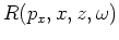
As for the transformation in the conventional plane-wave migration, we can transform offset domain CIGs
axis.
In plane-wave migration in tilted coordinates, the subsurface offset direction is not necessary the geologic dip direction,
but is usually closer to the dip direction for steeply dipping reflectors, than the conventional horizontal subsurface offset.
As for the transformation in the conventional plane-wave migration, we can transform offset domain CIGs
 of plane-wave source corresponding to
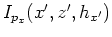
to angle domain CIGs
of plane-wave source corresponding to
to angle domain CIGs
 in tilted coordinates by applying
 |
(11) |
where
 and
and  are wavenumbers corresponding to and
  , respectively.
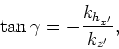
For each angle
, respectively.
For each angle  , we rotate the image
back to vertical Cartesian coordinates.
The angle domain CIGs of all possible plane-wave sources are then stacked in vertical Cartesian coordinates.
, we rotate the image
back to vertical Cartesian coordinates.
The angle domain CIGs of all possible plane-wave sources are then stacked in vertical Cartesian coordinates.
We can also transform the subsurface offset CIGs obtained by plane-wave migration in tilted coordinates into
horizontal offset and vertical offset CIGs, and merge them using equation 8 after transforming
them into angle domain CIGs, similarly to reverse-time migration.
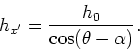
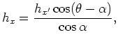
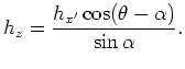
Equations 6 and 7 are the relationships linking the geologic offset  ,
horizontal offset and vertical offset
,
horizontal offset and vertical offset  .
The horizontal and vertical offsets are two special cases and the relationship can be generalized to a general-direction offset.
If the angle between the general-direction offset
.
The horizontal and vertical offsets are two special cases and the relationship can be generalized to a general-direction offset.
If the angle between the general-direction offset  and geologic offset is
  ,
the relationship between them is
,
the relationship between them is
 |
(12) |
The angle in equation 12 for  is
is  and for
  is
is
 .
From equation 12, the geologic offset is the optimal offset to generate angle domain CIGs and
the further the offset direction is from the dip direction, the larger the subsurface offset we need
given the same opening angle.
For the tilted coordinate system
, the angle between the subsurface offset and geologic offset is
.
From equation 12, the geologic offset is the optimal offset to generate angle domain CIGs and
the further the offset direction is from the dip direction, the larger the subsurface offset we need
given the same opening angle.
For the tilted coordinate system
, the angle between the subsurface offset and geologic offset is  .
Therefore, the subsurface offset in tilted coordinates and the geologic offset can be linked by
the following relationship:
.
Therefore, the subsurface offset in tilted coordinates and the geologic offset can be linked by
the following relationship:
 |
(13) |
From equations 13, 6 and 7, the subsurface offset in tilted coordinates , vertical offset and horizontal offset are linked by the following relationship:
 |
|
|
(14) |
 |
|
|
(15) |
By equations 14 and 15, the offset domain CIGs in tilted coordinates
 can be decomposed into horizontal offset CIGs and vertical offset CIGs.
Vertical offset domain CIGs and horizontal offset domain CIGs of all possible plane-wave sources are stacked
after being rotated back to vertical Cartesian coordinates.
Being transformed to angle domain CIGs, they are merged using equation 8,
as with reverse-time migration.
can be decomposed into horizontal offset CIGs and vertical offset CIGs.
Vertical offset domain CIGs and horizontal offset domain CIGs of all possible plane-wave sources are stacked
after being rotated back to vertical Cartesian coordinates.
Being transformed to angle domain CIGs, they are merged using equation 8,
as with reverse-time migration.
hxgathers
Figure 3. Horizontal offset domain CIGs with the true velocity obtained by reverse-time migration. (a) For relatively flat
sediments, the energy focuses well at zero offset; (b) For steep salt flanks, the energy leaks to far offsets and the frequency is low.
|

|
|
|
|---|
|
|---|
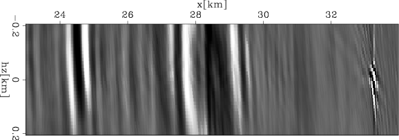
hzgather
Figure 4. Vertical offset domain CIGs with the true velocity obtained by reverse-time migration.
For the steeply dipping salt flank at  km, the energy focuses well at zero offset.
For the near-flat sediments at km, the energy focuses well at zero offset.
For the near-flat sediments at  km, the energy leaks to far offsets. km, the energy leaks to far offsets.
|
|---|
|
|
|---|
|
|
|
|
| Angle domain common image gathers for steep reflectors | |
|
Next: Numerical examples
Up: Shan and Biondi: Angle
Previous: Angle domain CIGs by
2007-09-18