|
|
|
|
|
|---|
|
bill
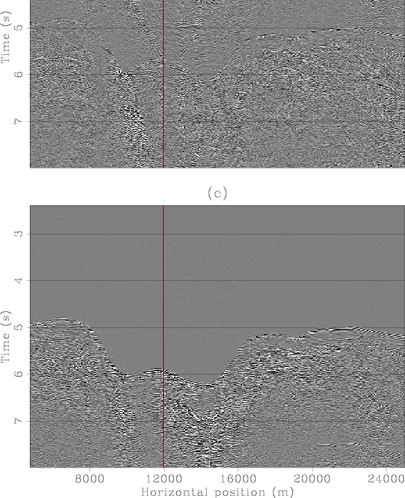
Figure 4. Prediction of 3D multiple with 2D SRME. Panel (a) is an inline common-offset section from a 3D survey. Panel (b) is an offset gather. Panel (c) is the inline common-offset section of the predicted multiple with 2D SRME and panel (d) is the offset gather of the predicted multiple. Notice that the prediction is good away from the canyon (the arrival times of the predicted multiple match those of the data) but no in the canyon where the predicted arrival times of the multiple are larger due to the crossline dip of the canyon. |
|
|
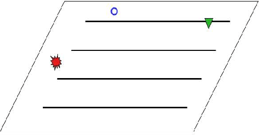
Prediction of multiples from reflectors with crossline dip, and diffracted multiples, especially those from scatterers with a cross-line offset component, cannot be accurately achieved with 2D SRME. Predicting these multiples requires the much more expensive 3D SRME. If the acquisition of the 3D survey is regular and dense enough, the survey apertures large enough in both in-line and cross-line directions, and there is no feathering, 3D SRME performs well. With standard marine streamer acquisition, however, the sampling in the cross-line direction is too coarse, the cross-line aperture is too narrow, short offsets are not recorded and feathering and acquisition obstacles make the acquisition geometry irregular. Any multiple whose surface bounce is not recorded can not be predicted by 3D SRME. Again, diffracted multiples, and multiples from a reflector with significant crossline dip pose the most serious problem because their surface bounce is likely to lie way outside the relatively narrow recording patch. Figure 5 shows a schematic map view of this situation. The empty circle represents the surface bounce of the multiple and, since there is not detector at that location, 3D SRME cannot predict that multiple. We do not need a particularly convoluted subsurface for this situation to arise in practice. All it takes is crossline dip of the water-bottom or the multiple-generating surface, or the presence of diffractors. These multiples, therefore, need to be removed by other methods (, ) or the data need to be interpolated and extrapolated to a dense, large aperture grid (, ,,,,). Interpolation is complicated by the coarse sampling that may introduce aliasing in the steep flanks of the multiple multiple moveout curves. Also, internal multiples cannot be predicted by SRME, unless the data is successively datumed to every multiple-generating interface. This is obviously a time-consuming process that is seldom, if ever, carried out. In most situations this is not a serious drawback, however, since internal multiples are usually weak. The exception is internal multiples from very strong reflectors such as salt boundaries.
|
|---|
|
3dsrme-sktch1
Figure 5. Schematic map view of a simple situation in which 3D SRME can not predict a multiple. The subsurface has significant crossline dip such that the surface bounce of the multiple (indicated by the empty circle), lies outside of the recording patch and therefore the multiple can not be predicted from the data. |
|
|
|
|
|
|