|
|
|
|
| Inline | ||||
| Min CMP | Max CMP | Min OFF (m) | Max OFF (m) | Aperture (m) |
| 9000 | 17000 | -750 | 250 | 8000 |
| Crossline | ||||
| Min CMP | Max CMP | Min OFF (m) | Max OFF (m) | Aperture (m) |
| 10000 | 14000 | -600 | 600 | 4000 |
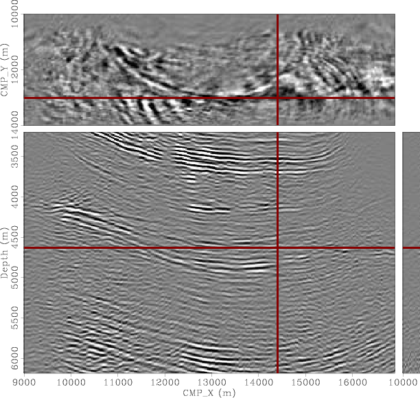
The result of the shot profile migration is a five-dimensional cube that is challenging to visualize. I will show some of the more common prestack subsets of the data to give an idea of the mapping of both primaries and multiples in the migrated domain. Figure 8 shows the 3D image cube taken at zero inline and zero crossline subsurface offsets. The top panel shows a depth slice at 4630 m where there is a hint of a multiple cutting through the primary reflections shown in the inline section (left panel) and pointed to by the arrow. This inline section is taken at CMP-Y=13000 m. The right panel shows the crossline section at CMP-X=14400 m. It is very difficult to discriminate which of these subsalt reflections are primaries and which are multiples without the help of prestack migrated images. The image in the crossline direction (right panel) is not nearly as clear because of the relatively few crossline CMPs that went into the prestack migration. This makes the identification of multiples in that panel even more difficult.
|
|---|
|
3dzoff
Figure 8. Shot profile migration. Zero subsurface offset cube. Top panel is a depth slice at 6430 m, left panel is the inline section at crossline 13000 m and right panel is the crossline section at inline 14400 m. |
|
|
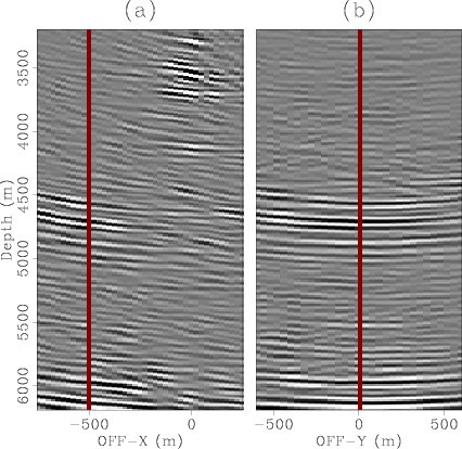
Ideally, the primaries should migrate to zero inline and zero crossline subsurface offsets. Errors in migration velocity and illumination problems may make them shift away from zero subsurface offsets, but in most situations these shifts away from zero subsurface offset are minor when compared to those of the multiples for which the difference between propagation and migration velocity is large. Therefore, we can expect that the primaries and the multiples be relatively easy to identify by their mapping in both the inline and crossline subsurface offsets. Figure 9 shows one 3D SODCIG taken at the spatial location CMP-X=14400 m and CMP-Y=13000 m (see Figure 8). The inline offset gather (panel (a)), corresponds to OFF-Y=0 while the crossline offset gather (panel (b)), corresponds to OFF-X=-500 m. In the inline offset gather we see that the primaries map near zero offset (above 3000 m) whereas the multiples map entirely to the negative subsurface offsets (around 4500 m and below 5500 m). Since the crossline offset gather is taken at the inline offset of the multiple (-500 m), the primaries are absent and the multiples map to both positive and negative subsurface offsets. This is a consequence of the geometry of acquisition that had positive inline surface offsets only but positive and negative crossline surface offsets. Notice also that more subsurface offsets, specially in the crossline direction, should have been computed in order to capture the multiples in their entirety.
|
gather-14400-13000
Figure 9. Shot profile migration. SODCIG at CMP-X=14400 m and CMP-Y=13000 m. Panel (a) is the inline offset gather taken at OFF-Y=0 and panel (b) is the crossline offset gather taken at OFF-X=-500 m. |
|
|---|---|
|
|
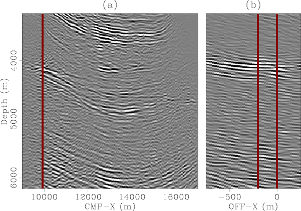
Figure 10 shows a subset of the five dimensional hyper-cube taken at CMP-Y=13000 m and OFF-Y=0 m. There is, therefore, no crossline information on this figure. Panels (a) and (c) show the inline sections at zero and -400 m inline subsurface offsets respectively, while the middle panel shows the inline gather at CMP-X=14400. Since the crossline offset is zero in all the panels, we can expect to see the primaries near the zero inline offset in panel (b) and as the dominant reflections in panel (a). The multiples (at least those that did not map away from zero crossline offset), we can expect to find at the negative inline offsets in panel (b) and as the dominant reflections in panel (c). Notice how it would have been very hard to visually distinguish primaries and multiples without the aid of these prestack images.

|
|---|
|
inline1-0-13000
Figure 10. Inline section and inline offsets at CMP-Y=13000 m and OFF-Y=0. Panel (a) is the inline section at zero inline offset. Panel (b) is the inline offsets at CMP-X=14400 m and Panel (c) is the inline section at -400 m inline offsets. Panel (a) should be mostly primaries while panel (c) should be mostly multiples. |
|
|
To take an even closer look at the multiples, Figure 11 shows a similar figure to Figure 10 but for CMP-X=9900 m. This time both panels (a) and (c) correspond mostly to multiples. An interesting observation is that the residual moveout of the multiple in panel (b) seems to have its bottom away from zero inline subsurface offset, indicating perhaps a diffracted multiple. Furthermore, recall that this inline plane is taken at zero crossline offset. The situation is even more manifest if the section is taken at a crossline offset away from zero.
|
|---|
|
inline2-0-13000
Figure 11. Inline section and inline-offset gather at CMP-Y=13000 m and OFF-Y=0. Panel (a) is the inline section at zero inline offset. Panel (b) is the inline offsets at CMP-X=9900 and Panel (c) is the inline section at -200 m inline offsets. Panel (a) is mostly primaries and panel (c) is mostly multiples. |
|
|

|
|---|
|
inline1-400-13000
Figure 12. Inline section and inline-offset gather at CMP-Y=13000 m and OFF-Y=-400. Panel (a) is the inline section at zero inline offset. Panel (b) is the inline offsets at CMP-X=14400 and Panel (c) is the inline section at -500 m inline offsets. Panel (a) has some contributions from primaries and multiples whereas panel (c) should be almost exclusively multiples. |
|
|
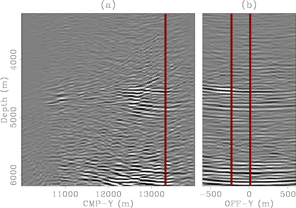
Finally, to illustrate the mapping of the multiples in the crossline direction, Figure 13 shows the subset taken at CMP-X=14000 m and OFF-X=0. As with the previous two figures, panel (a) corresponds to the crossline section at OFF-Y=0 while panel (c) is a similar section at OFF-Y=-400 m. The middle panel corresponds to the crossline offset gather. Here also the primaries should map to panel (a) while some of the multiples (those that did not map away from zero inline offset), should map to panel (c). In panel (b) we can see that the primaries map near zero crossline offset while the multiples map away from zero both to positive and negative subsurface offsets. Similarly, Figure 14 shows the subset taken at the same CMP-X location but at OFF-X=-600 m. Both panels (a) and (c) should now correspond to multiples and no primaries should be mapped to any of these panels.

|
|---|
|
xline1-0-14000
Figure 13. Shot profile migration. Crossline section and crossline offsets at CMP-X=14000 m and OFF-X=0. Panel (a) is the crossline section at zero crossline offset. Panel (b) is the crossline offsets at CMP-Y=12760 m and Panel (c) is the crossline section at -400 m crossline offsets. Panel (a) should be mostly primaries while panel (c) should be mostly multiples. |
|
|
|
|---|
|
xline1-600-14000
Figure 14. Shot profile migration. Crossline section and crossline offsets at CMP-Y=14000 m and OFF-X=-600. Panel (a) is the crossline section at zero crossline offset. Panel (b) is the crossline offsets at CMP-Y=13300 m and Panel (c) is the crossline section at -240 m crossline offsets. Both panels (a) and panel (c) should be multiples. |
|
|
|
|
|
|