Next: Apex-shifted Radon Transform
Up: Image space attenuation of
Previous: Diffracted multiple
In this section I show how to exploit the difference in residual
moveout between primaries and multiples in ADCIG's given by
Equation 24 to design a Radon transform that focuses the
primaries and multiples to separate regions of the Radon domain.
The general expression for the Radon transform in the angle domain is
(, )
 |
(25) |
where  is a measure of curvature and
  is the function
that approximates the residual moveout of the multiples as a function
of the aperture angle
is the function
that approximates the residual moveout of the multiples as a function
of the aperture angle  .
() and () used the
tangent-squared approximation of Biondi and Symes (2004)
.
() and () used the
tangent-squared approximation of Biondi and Symes (2004)
 |
(26) |
but for the focusing of the multiples a more accurate approximation is given by
Equation 24:
![\begin{displaymath}
g(\gamma)=\frac{1}{1+\rho}\left[\frac{\cos\gamma(\rho^2-(1-\rho^2)\tan^2\gamma)}{\sqrt{\rho^2-\sin^2\gamma}}-\rho\right].
\end{displaymath}](img105.png) |
(27) |
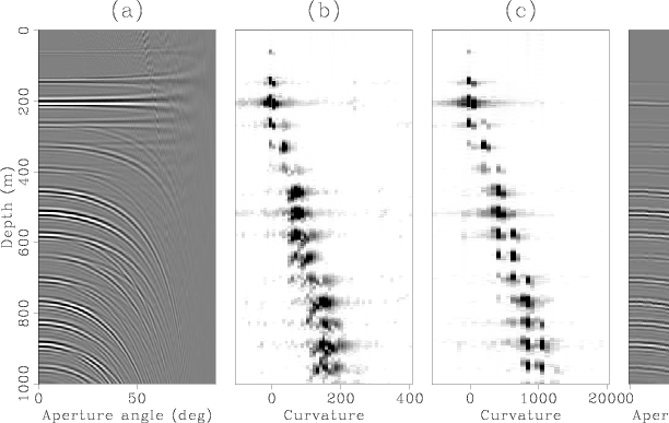
This approximation is more accurate because it takes into account ray bending at the
multiple-generating interface. This is illustrated in
Figure 7 which shows a comparison of the Radon transforms defined be
equations 27 and 26 applied to a synthetic ADCIG.
Notice that the focusing of the primaries does
not change since their moveout is zero. The multiples, on the other hand, are
better focused with the new transform (panel (c)) which more closely follows
their residual moveout in the ADCIGs. The better focusing of the multiples
translates to a better estimation of the multiple model (compare panels (d) and (e)
computed from panels (b) and (c), respectively). Notice, however, that this synthetic
ADCIG
has high aperture angles for which the difference between the two approximations is
greater. As the angle coverage decreases, so does this difference. In any event,
the better focusing of the multiples helps in separating them from the primaries.
|
|---|
synth1
Figure 7. Comparison of Radon transforms for a synthetic ADCIG.
Panel (a) shows the ADCIG. Panels (b) and (c) correspond to the envelopes of the Radon
transform of panel (a) computed with the straight-ray approximation and the ray-bending
approximation respectively. Panels (d) and (e) are the multiple models computed from panels
(b) and (c). The ovals highlight the improved accuracy afforded by the new transform
for the multiple model at the large aperture angles.
|
|---|
![[pdf]](icons/pdf.png) ![[png]](icons/viewmag.png)
|
|---|
Subsections
Next: Apex-shifted Radon Transform
Up: Image space attenuation of
Previous: Diffracted multiple
2007-10-24