Next: Discussion and Conclusions
Up: Vyas: SRMP
Previous: Reconstructing missing angles
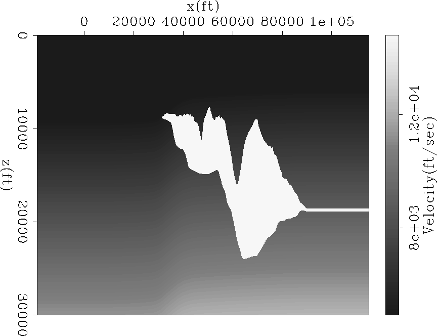
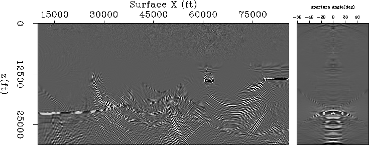
Moving to a more realistic and complex subsurface geometry, in this section I discuss the application of SRMP on the Sigsbee data set. Figure ![[*]](http://sepwww.stanford.edu/latex2html/cross_ref_motif.gif) and show the Sigsbee velocity model and the migrated image respectively. Figure shows the corresponding multiple model in the image space. The side face in these figures is a representative ADCIG corresponding to sediments, left of the salt body. Since we migrate with the correct velocity, primaries appear flat in the ADCIGs, and multiples show a frown since they are migrated with velocities higher than their actual velocities.
vel.sig
and show the Sigsbee velocity model and the migrated image respectively. Figure shows the corresponding multiple model in the image space. The side face in these figures is a representative ADCIG corresponding to sediments, left of the salt body. Since we migrate with the correct velocity, primaries appear flat in the ADCIGs, and multiples show a frown since they are migrated with velocities higher than their actual velocities.
vel.sig
Figure 12 Velocity model for the Sigsbee data
 imgtr.sig
Figure 13 Image and a representative ADCIG for Sigsbee data migrated with the true velocity


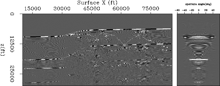
 multr.sig
Figure 14 Multiple model (in image space) and a representative ADCIG for the Sigsbee data migrated with the true velocity
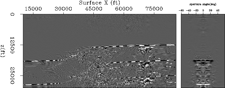
The complex velocity model and especially the salt body cause the multiples to image in a very complicated fashion. It is difficult to identify even the water-bottom multiples that image underneath the salt body. Our goal here is to analyze multiples modeled by SRMP and improve our estimate if we have some missing parts in our model. Ideally, we would like to look at multiples in a domain where they can be easily identified and understood. To accomplish this I use water velocity as the migration velocity. Not all multiples travel at the water velocity, but many that emanate from shallow layers almost do that. Figures and show the image and the multiple model, with an ADCIG on the side. The first- and second-order water-bottom multiples look much more interpretable as we used water velocity for migration. These multiple events also appear flat in ADCIGs.
imgwv.sig
Figure 15 Image and a representative ADCIG for Sigsbee data migrated with the water velocity
mulwv.sig
Figure 16 Multiple model (in image space) and a representative ADCIG for the Sigsbee data migrated with the water velocity
The Sigsbee data set has offsets of about 30000 ft. To illustrate the limitations of SRMP in the case of limited-offset recordings, I retain only near offsets (5000 ft) to model the multiples. In Figure , I compare the image (top) with the multiple model (bottom). Second-order multiples corresponding to the dipping part of the water bottom and salt canyon are present in the image but are not modeled using SRMP (compare circled events). These events correspond to the ray paths that tend to bounce back into the recording geometry, which we could not model because of limited recording offsets.
smloff.comp
Figure 17 A window extracted from the (a) image and (b) the multiple model after migrating with the water velocity.
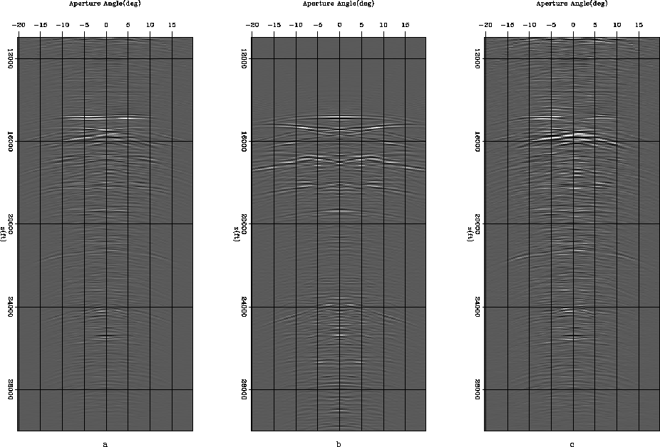
To demonstrate the possible use of angle gathers in SRMP, I focus on the dipping part of the first-order water-bottom multiple. The dip of that part is about  . Figure (a) shows the ADCIG drawn from the image around the location of the dipping water bottom. Figure (b) is the ADCIG of the multiple model at the same location. The first-order water-bottom multiple (at about a depth of 15000 ft) is illuminated at a much wider range of angles than it is actually modeled. If we subtract the multiples in the data space and then migrate the resulting data set, our image has some remnants of the multiple, which is understandable, since we did not model all the multiples that we recorded. Figure (c) is the ADCIG from the same location, but corresponding to the data for which we subtract modeled multiples in the data space. For the specific water-bottom multiple, the energy is removed close to the zero opening angle but is present at higher opening angles. This observation is similar to the one in the simple synthetic example discussed in the previous section.
adcig.sig
Figure 18 ADCIG for (a)the image, (b) the multiple model and (c) the image after multiple removal in the data domain
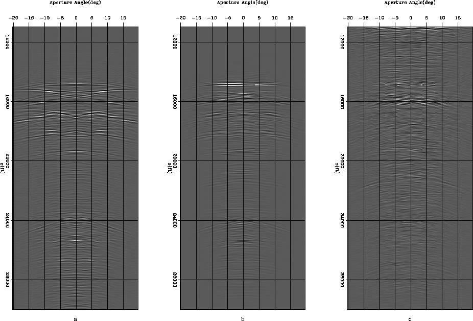
As in the simple synthetic example applying adaptive subtraction in the image domain gives us a better chance of removing this class of multiples. This is because in the angle space, multiples appear flat when migrated with the perfect velocity, and it is relatively straightforward for the matching filters to adaptively match the pattern of recorded multiples. When the velocity is not perfect, and multiples show curvature, it may be better to use Radon transforms to reconstruct missing multiples at higher opening angles. To draw a comparison for the given example, I plot in Figures (a), (b) and (c) the ADCIG for the modeled multiple, the reconstructed multiple using the matching filter, and the multiple-free gather after subtraction in image space. The angle gather looks relatively cleaner after subtraction in the image domain (right panel).
adcig2.sig
Figure 19 ADCIG for (a) the multiple model, (b) the reconstructed multiple model and (c) the image after multiple removal in image domain
Since we carried out migration with the water velocity, we now demigrate with the water velocity and re-migrate with the true velocity to obtain a multiple-free image. This proposition appears expensive, but may be useful when the multiple noise is overwhelming. Again, an alternative may be to use the true velocity but use Radon transforms to infill missing angles and assist adaptive subtraction in the angle domain.
Next: Discussion and Conclusions
Up: Vyas: SRMP
Previous: Reconstructing missing angles
Stanford Exploration Project
5/6/2007