

Next: Practice considerations
Up: Shan et al.: Plane-wave
Previous: Conical-wave source migration
A 3D plane-wave source is specified by two ray-parameters, px and py. Given the velocity at the surface vz0, we
can calculate the propagation direction of the plane-wave source at the surface from the two ray-parameters.
For each plane-wave source, we rotate the Cartesian coordinates, so that the extrapolation direction
of the new coordinates is close to the propagation direction of the plane-wave.
In 3D, the propagation direction of a plane-wave source is defined by two angles: the azimuth angle  and the take-off angle
  .
Given the velocity at the surface vz0 and a plane-wave source with a ray parameter pair (px py), its propagation direction at the surface is defined by the vector (qx,qy,qz), where
|  |
(13) |
| (14) |
| (15) |
The azimuth angle and take-off angle of the plane-wave source are calculated
from the vector (qx,qy,qz) as follows:
|  |
(16) |
| (17) |

Rotations in 3D are specified by the axis of rotation and rotation angle. They can be described by a rotation matrix.
For example, a rotation about the z-axis by an angle  (Figure
 ![[*]](http://sepwww.stanford.edu/latex2html/cross_ref_motif.gif) ) is
) is
|  |
(18) |
To design a coordinate system with an extrapolation direction parallel
the propagation direction of the plane-wave source (qx,qy,qz),
we rotate the coordinates in two steps.
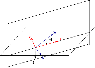
First we rotate about the z-axis by an angle
 (equation 18) shown in Figure
 ![[*]](http://sepwww.stanford.edu/latex2html/cross_ref_motif.gif) .
Second we rotate about the
y1-axis by an angle
.
Second we rotate about the
y1-axis by an angle  (Figure
 ![[*]](http://sepwww.stanford.edu/latex2html/cross_ref_motif.gif) ) as follow:
) as follow:
rottilt
Figure 2 Rotation about the axis y1 by  |
|  |

|  |
(19) |
Combining the two rotations, we have the rotation from original coordinates
to the new tilted coordinates as follows,
|  |
(20) |
It is easy to verify that the depth axis of the new coordinates parallels the propagation
direction (qx,qy,qz).
In practice, we do not use the direction exactly paralleling the propagation of the plane-wave source at the surface.
Considering that the velocity usually increases with the depth,
the propagation direction of a plane-wave source becomes
increasingly horizontal. So we usually choose a tilting angle  that is a little bigger than
  .
coordinates
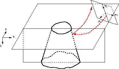
Figure 3 A plane-wave source and its coordinates to image the salt body.(x,y,z)
is the original Cartesian coordinates. (x2,y2,z2) is the new tilted coordinates. The dashed line with
arrows are the source and receiver rays of the plane-wave source. The extrapolation direction of the new
coordinates z2 axis is closer to the propagation direction of the plane-wave source.

Figure ![[*]](http://sepwww.stanford.edu/latex2html/cross_ref_motif.gif) shows
a typical coordinate system used for a plane-wave source to image a salt dome.
The dashed lines with arrows show the propagation direction of the source and receiver waves for the plane-wave source. (x,y,z) is the
Cartesian coordinate system, and (x2,y2,z2) is the tilted coordinates for the plane-wave source. The extrapolation direction of
the new coordinates, which parallels z2-axis, is much closer to the propagation direction of the plane-wave source
than the conventional vertical extrapolation direction.
shows
a typical coordinate system used for a plane-wave source to image a salt dome.
The dashed lines with arrows show the propagation direction of the source and receiver waves for the plane-wave source. (x,y,z) is the
Cartesian coordinate system, and (x2,y2,z2) is the tilted coordinates for the plane-wave source. The extrapolation direction of
the new coordinates, which parallels z2-axis, is much closer to the propagation direction of the plane-wave source
than the conventional vertical extrapolation direction.
For conical-wave source migration, we can similarly design tilted coordinates for
each conical source. In contrast to the 3D plane-wave source migration,
we apply the second rotation directly without rotating the azimuth
of the data. Given the conical-wave source with a ray parameter px and the surface
velocity vz0, we rotate the velocity and the surface data along y-axis by a angle of
 and migrate the data in the new coordinates.
This usually works when the in-line direction is the predominant
dip direction in the subsurface. When there are steep dips in the cross-line direction,
it is still difficult to image these dips with conical-wave migration in tilted coordinates.
In contrast, 3D plane-wave migration in tilted coordinates rotate the data and model into a general
direction dependent on the propagation direction and it can image these cross-line direction dips.
ppanel
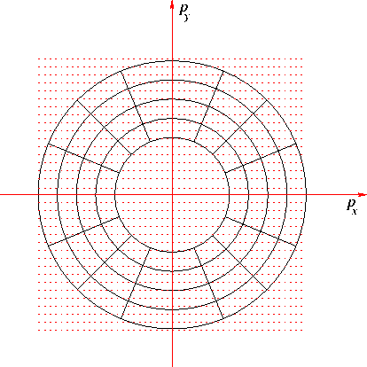
Figure 4 The dots represent all possible plane-wave sources. The circles are the contour of their take-off angles and the smallest circle represents plane-wave sources with a take-off angle of  . The radial lines show the contour of azimuth angles. All possible plane-wave sources are divided into small cells. The plane-wave sources in a cell have a similar take-off and azimuth angle and share a coordinate system.


Next: Practice considerations
Up: Shan et al.: Plane-wave
Previous: Conical-wave source migration
Stanford Exploration Project
5/6/2007


![]() (Figure
(Figure ![[*]](http://sepwww.stanford.edu/latex2html/cross_ref_motif.gif) ) is
) is

![]() (equation 18) shown in Figure
(equation 18) shown in Figure ![[*]](http://sepwww.stanford.edu/latex2html/cross_ref_motif.gif) .
Second we rotate about the
y1-axis by an angle
.
Second we rotate about the
y1-axis by an angle ![]() (Figure
(Figure ![[*]](http://sepwww.stanford.edu/latex2html/cross_ref_motif.gif) ) as follow:
) as follow:


![[*]](http://sepwww.stanford.edu/latex2html/cross_ref_motif.gif) shows
a typical coordinate system used for a plane-wave source to image a salt dome.
The dashed lines with arrows show the propagation direction of the source and receiver waves for the plane-wave source. (x,y,z) is the
Cartesian coordinate system, and (x2,y2,z2) is the tilted coordinates for the plane-wave source. The extrapolation direction of
the new coordinates, which parallels z2-axis, is much closer to the propagation direction of the plane-wave source
than the conventional vertical extrapolation direction.
shows
a typical coordinate system used for a plane-wave source to image a salt dome.
The dashed lines with arrows show the propagation direction of the source and receiver waves for the plane-wave source. (x,y,z) is the
Cartesian coordinate system, and (x2,y2,z2) is the tilted coordinates for the plane-wave source. The extrapolation direction of
the new coordinates, which parallels z2-axis, is much closer to the propagation direction of the plane-wave source
than the conventional vertical extrapolation direction.
![]() and migrate the data in the new coordinates.
This usually works when the in-line direction is the predominant
dip direction in the subsurface. When there are steep dips in the cross-line direction,
it is still difficult to image these dips with conical-wave migration in tilted coordinates.
In contrast, 3D plane-wave migration in tilted coordinates rotate the data and model into a general
direction dependent on the propagation direction and it can image these cross-line direction dips.
and migrate the data in the new coordinates.
This usually works when the in-line direction is the predominant
dip direction in the subsurface. When there are steep dips in the cross-line direction,
it is still difficult to image these dips with conical-wave migration in tilted coordinates.
In contrast, 3D plane-wave migration in tilted coordinates rotate the data and model into a general
direction dependent on the propagation direction and it can image these cross-line direction dips.
