


Next: Mapping of PS-ADCIGs
Up: Imaging of converted-wave Ocean-bottom
Previous: Chapter 5: PS common-azimuth
PS angle-domain transformation
This appendix presents the transformation
from the subsurface-offset domain into the angle-domain
for converted-wave data.
The derivation follows the well-known equations for apparent slowness
in a constant-velocity medium in the neighborhood of the reflection/conversion
point. This derivation is consistent with the one presented by
Fomel (2001);Sava and Fomel (2003); and
Biondi (2005).
The expressions for the partial derivatives of the total
traveltime with respect to the image point coordinates ( ) are
as follows Rosales and Rickett (2001):
) are
as follows Rosales and Rickett (2001):
| 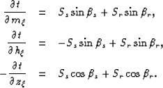 |
|
| |
| (63) |
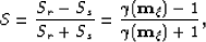
Where Ss and Sr are the slowness (inverse of velocity) at the
source and receiver locations, respectively.
Figure ![[*]](http://sepwww.stanford.edu/latex2html/cross_ref_motif.gif) illustrates all the angles in this discussion. The angle
illustrates all the angles in this discussion. The angle  is the
direction of the wave propagation for the source, and the angle
is the
direction of the wave propagation for the source, and the angle  is the
direction of the wave propagation for the receiver.
is the
direction of the wave propagation for the receiver.
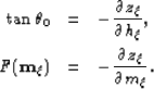
Throughout these set of equations, we obtain:
| 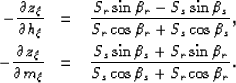 |
|
| (64) |
At this step, I define two angles,  and
and  , to relate and as follows:
| 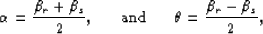 |
(65) |
as I discussed in Chapter 3, the angles and  ,for the case of converted-wave data, are the half-aperture angle
and the pseudo-geological dip, respectively.
,for the case of converted-wave data, are the half-aperture angle
and the pseudo-geological dip, respectively.
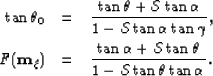
Following the change of angles suggested on equation ,
and by following basic trigonometric identities,
we can rewrite equations as follows:
| 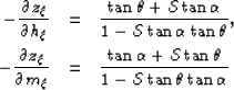 |
|
| (66) |
where,
|  |
(67) |
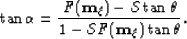
I introduce the following notation in equation :
|  |
|
| (68) |
In the notation ,  is the pseudo-reflection angle,
and
is the pseudo-reflection angle,
and  is local image-dips. The bases for this
definition resides in the conventional isotropic single-mode PP case. For this case,
the pseudo-reflection angle is the
reflection angle, and the field represents the
geological dip Fomel (1996).
Using the notation into equation , I
present the equations
is local image-dips. The bases for this
definition resides in the conventional isotropic single-mode PP case. For this case,
the pseudo-reflection angle is the
reflection angle, and the field represents the
geological dip Fomel (1996).
Using the notation into equation , I
present the equations
|  |
(69) |
| (70) |
Following basic algebra, equation reduces to
|  |
(71) |
Substituing equation into equation ,
and following basic algebraic manipulations, we obtain equation
in Chapter 3.
Next: Mapping of PS-ADCIGs
Up: Imaging of converted-wave Ocean-bottom
Previous: Chapter 5: PS common-azimuth
Stanford Exploration Project
12/14/2006